
Share the geometry
Send the current drawing or model, revision, material or grade, and the features that control fit, function or appearance.
Engineering across our three services
Explore practical engineering scenarios across mold tooling, molded components and CNC machining. Each example shows the questions our engineers resolve with you, from the initial geometry to an agreed validation plan.
Illustrative engineering scenarios for technical planning and project discussion.
Illustrative scenarios
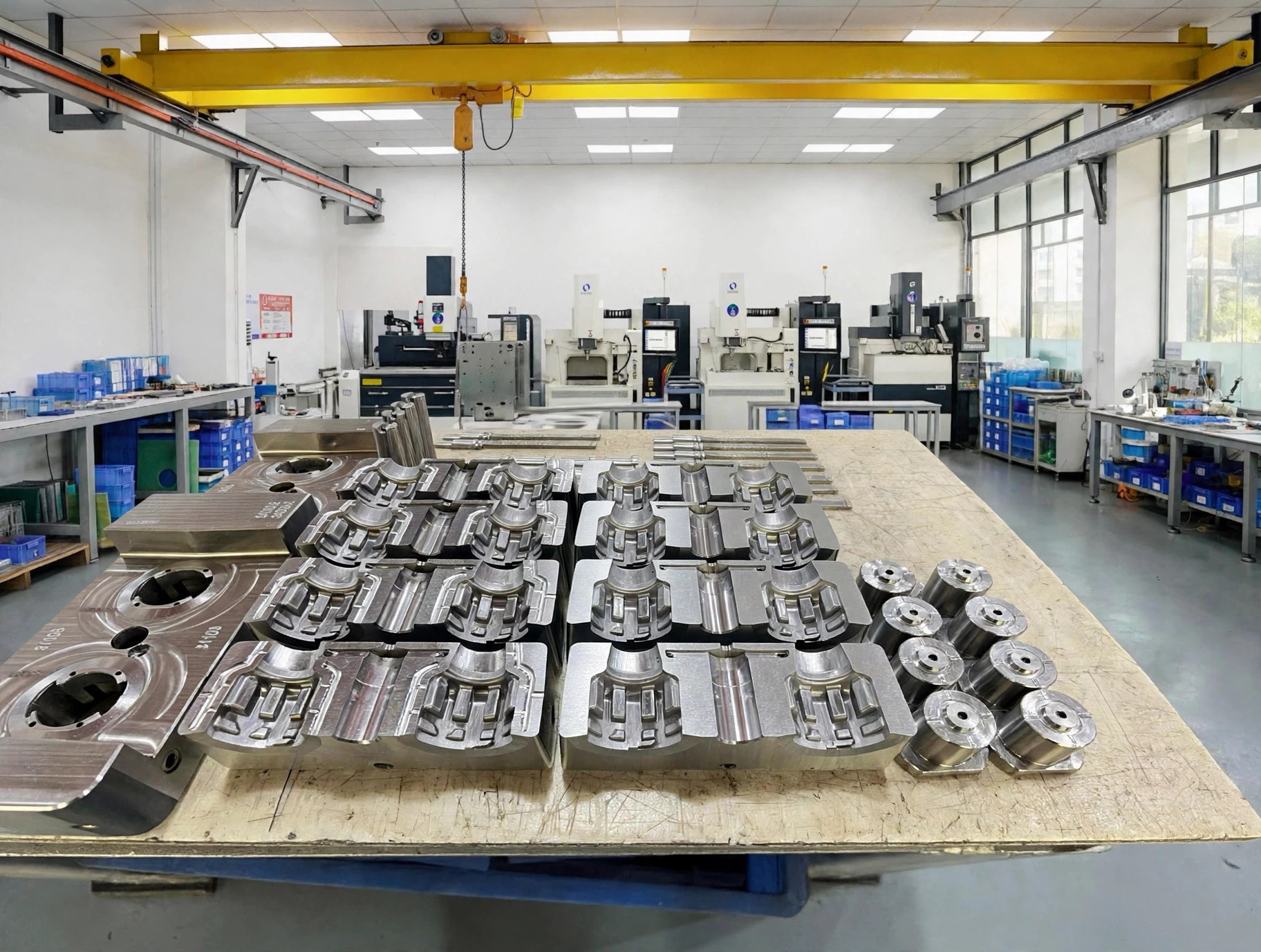
Use these examples to identify the decisions that matter for your part. The photographs provide visual reference for component or manufacturing geometry; each project’s material, process and acceptance requirements must be confirmed from its own drawings and application.
6 engineering examples available.
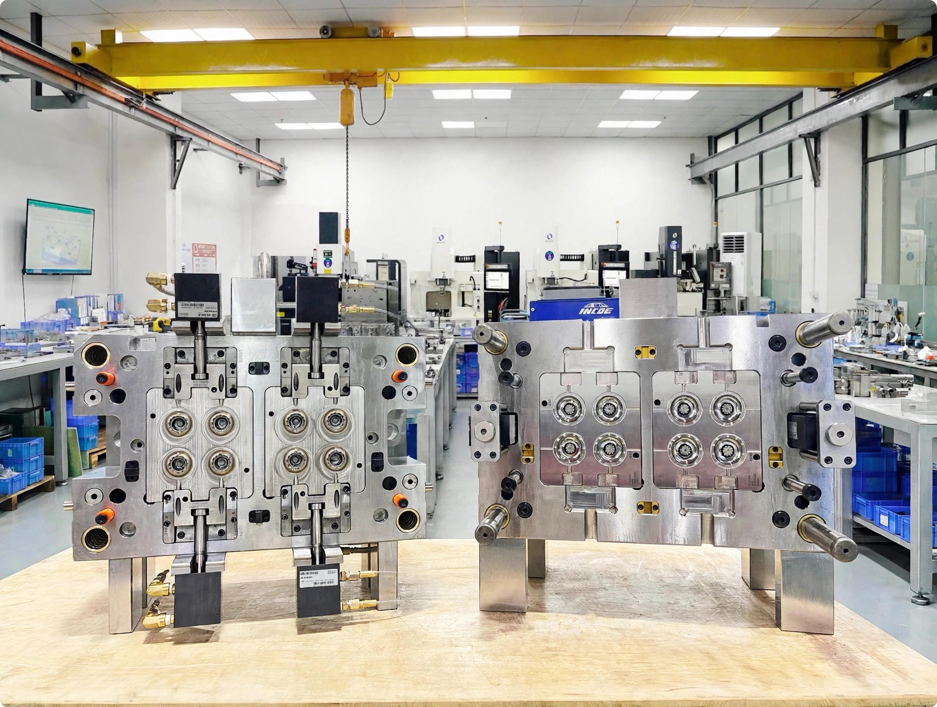
Cavity layout and repeatability
A repeated part geometry calls for a cavity layout that fits the production plan, receiving press and dimensional requirements.
For this illustrative scenario, the brief is to plan tooling for repeated molded parts while making the assumptions behind cavity count, filling, cooling and acceptance visible. The important starting point is the part and the intended production context. Cavity count affects the tool layout, but it also needs to fit the press interface, expected release quantities, cycle assumptions and the way samples will be evaluated.
Before trials, agree the molding conditions to record and the sample coverage needed across cavities. Define how dimensional and appearance characteristics will be reviewed, how cavities will be identified in the records, and who will assess any variation that matters to assembly or function. Tooling acceptance should follow criteria written for the part and order.
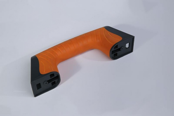
Material interface and tool coordination
A rigid component with a second material region needs coordinated interfaces, transfer or rotation, and an agreed validation plan.
This illustrative brief considers tooling for a component made with two material regions. The design needs to preserve the intended interface, registration, appearance and compatibility with the selected machine. A useful review starts with the part’s function and the actual material grades, then connects those requirements to the tool layout and molding sequence.
Agree the material pair, part condition, appearance boundary and critical dimensions before evaluating samples. If the interface has a retention or functional role, define a suitable test method and acceptance basis for that use. Record relevant first-shot and second-shot observations so the team can decide whether the tool and process need adjustment before release. Base acceptance on the selected grades and intended use.
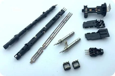
Location, protection and retention
Metal contacts or inserts need to remain correctly located while their intended mating surfaces stay usable after molding.
In this illustrative scenario, the project is to mold plastic around metal inserts with a clear specification for insert location, exposed surfaces and functional acceptance. The design review needs to consider both the insert as supplied and the molded part as assembled. Drawings should distinguish the surfaces that become enclosed from threads, contacts or mating faces that must remain available for a later connection.
Choose checks around the features that control the application. The team can agree which insert positions and exposed features will be measured, the method and sampling, and whether separate retention or functional tests are needed. Dimensional inspection and an application-specific pull, electrical or assembly test answer different questions; each should have its own defined basis. Acceptance should follow the drawing and intended use rather than an assumed generic force value.
Substrate fit and overmold boundary
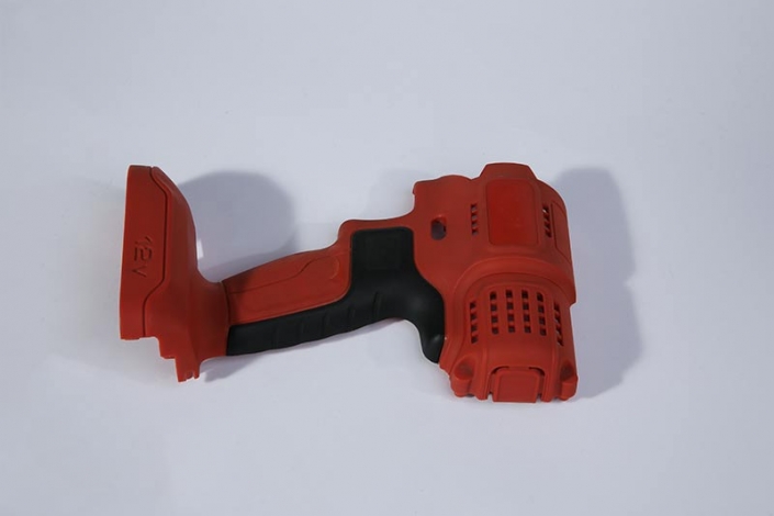
A grip or protective region needs to align with the substrate, visible boundary and intended assembly function.
This illustrative scenario frames a molded component with a secondary material region. The substrate’s condition and the finished part’s function are central: how the substrate is supplied, identified and located can affect the interface, boundary and fit. Before tooling choices are made, the brief should separate the desired appearance from grip, retention, sealing or other functional needs so each can be reviewed against the real assembly.
Define the approved appearance and boundary, then identify the dimensions that control mating or assembly. Specify adhesion, retention or functional tests only where they are relevant to the part’s use, including conditioning when the environment requires it. The team should review sample findings against the agreed substrate condition, materials and process assumptions. A material choice by itself does not establish that a bond or seal will meet the application requirement.
Datums, access and final condition
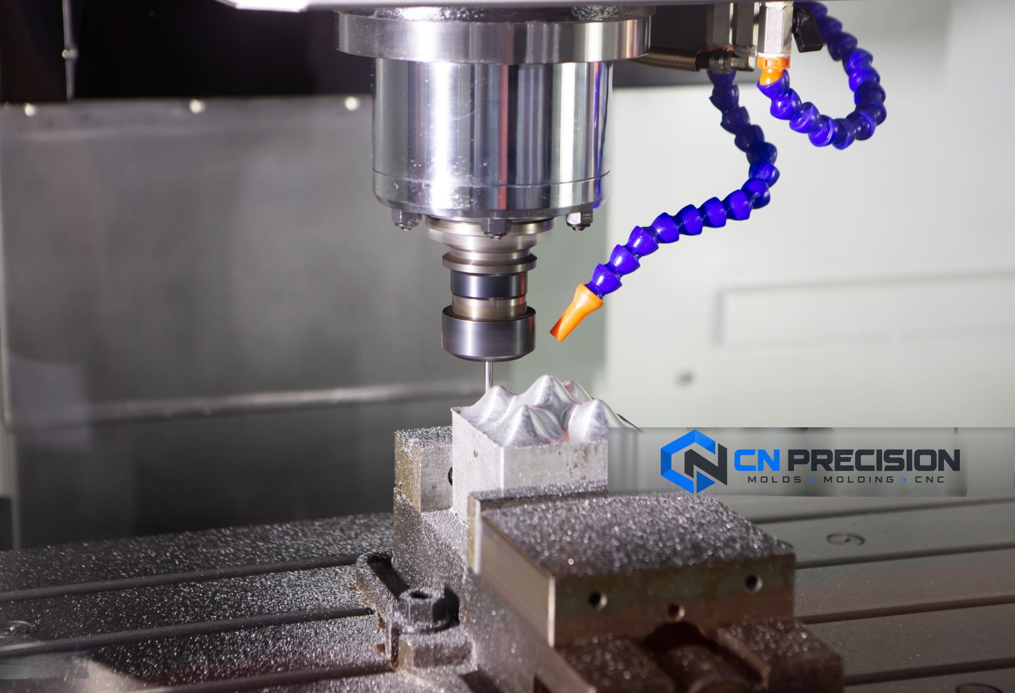
The functional relationship between surfaces and features matters as much as each individual dimension.
This illustrative machining brief concerns a custom component whose mating features must be understood from the drawing and assembly. A list of tight dimensions alone may not explain which relationships control fit. Review begins by identifying functional datums, material grade and condition, and the faces or features that locate against other parts. The finished condition also matters when later processing can affect a critical surface or dimension.
Agree dimensional and geometric checks from the drawing requirements, along with method and sampling. First-article documentation, customer approval holds and ongoing lot inspection should be distinguished so the records match the decision being made. If a final treatment can affect a critical feature, make the acceptance condition explicit and determine whether checks occur before, after or at both stages. Define the acceptance requirement for the finished part and its intended mating features.
From example to brief
A clear first discussion connects the part to how it will be made, assembled and accepted. Share what is known, flag what is still open, and the team can identify which questions belong in the manufacturing scope.
Send the current drawing or model, revision, material or grade, and the features that control fit, function or appearance.
Explain the mating parts, production context, target quantities and any environmental or performance requirements that shape the design.
Identify the checks, sample conditions and records your team needs to make a decision. The method and scope can then be aligned to the actual project.
Your project, clearly scoped
Tell us what you are making, what needs to fit or perform, and where the design still has open questions. A drawing or model can help frame the next discussion.