CNC turned parts · Precision turning in China

CNC Turned Parts and Precision Turning Services

Custom CNC turned parts—shafts, sleeves, bushings and threaded components in metal and engineering plastics, made to your drawing and agreed finished condition.

Bring the fits, functional surfaces and assembly requirements. WOKE Molds connects precision turned parts with secondary operations, finishing and inspection in one project scope, including Swiss turned parts for small, long components.

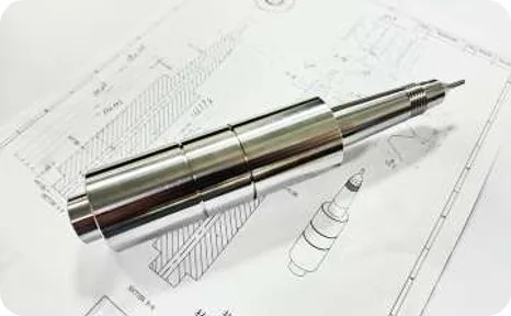
CNC turned parts: a stepped precision shaft resting on an engineering drawing
Stepped diameters and shoulder locations define the shaft profile.

Parts and function

Start with the features that must fit

Turning is a strong candidate when the main geometry follows a rotational axis. These part families help frame a drawing review for automation equipment, instruments and other industrial assemblies.

Stepped metal shaft resting on an engineering drawing

Which features make a shaft work?

Bearing and locating journals, axial shoulders, seal tracks, tapers and threaded ends may each serve a different purpose. Mark which surfaces locate the assembly and which may be used for holding or support.

Provide the bearing or mating-fit callouts, shoulder locations, required surface texture and any geometric controls. Identify permitted center holes and protected contact areas. Acceptance must connect the fit diameters with their specified axis relationships and axial seating dimensions.

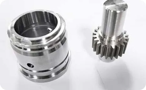
Cylindrical sleeve beside a metal gear shaft

What defines an acceptable sleeve?

A sleeve starts with the relationship between its bore, outside diameter and end faces. Thin sections, interrupted walls or cross-holes add clamping and deburring questions. The application determines whether wear, sliding, insulation or sealing is important.

Provide bore size and depth, OD fit, wall geometry and end-face requirements. State whether inspection is in the free or defined restrained condition. Review gear or spline features shown in a complete component as additional operations within the full manufacturing route.

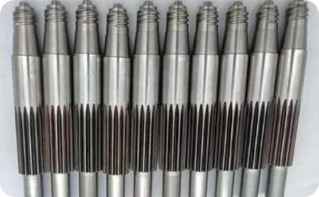
Row of metal shafts with threaded ends and splined sections

What matters beyond the thread diameter?

Threaded studs, adapters and rotational connectors need a defined mating interface. A thread near a shoulder or blind bottom may have less usable full-form length than the overall feature suggests.

Specify the thread standard, pitch, class, hand and usable engagement length. Include relief, lead-in and inspection requirements. Shafts with visible splines or teeth require assessment of those operations as well as the turned blank; include their specifications in the complete-part review.

Select a family to explore its requirements. Your complete drawing determines the material, route and acceptance basis.

Feature review

Make the small details explicit

Cylindrical sleeve beside a metal gear shaft

Bores, outside profiles and tooth features belong in the complete-part specification.

A section view is especially useful for a blind bore, internal groove or thread termination. It shows the access and functional length that a shaded model can hide.

How should I define stepped diameters and shoulders?

Identify each functional OD or ID and its mating-fit requirement. Dimension the axial seating faces and shoulder stack from the intended locating reference. Include corner radii or relief where a bearing, spacer or mating face must seat fully.

What makes a bore or taper accessible?

Show the entry diameter, depth, blind-bottom form and any interrupted surfaces. Define a taper by the applicable dimensions and acceptance requirement. Tool approach and internal reach need review independently of the accessible outside profile.

What information is needed for grooves and undercuts?

Provide groove width, depth, root radius and location from an accessible reference. Internal grooves also need entry clearance and space for the tool and chips. Identify sealing or retaining-ring functions so the required profile is clear.

How much usable thread is required near a shoulder?

State the standard, pitch, class and hand together with the usable full-form length. Show permitted runout, relief and lead-in. Tool exit space and gaging access are reviewed against the mating requirement, including blind internal threads.

Which edges and intersections need special attention?

Identify burr-sensitive cross-holes, bore intersections, thread starts and sealing edges. Define required edge breaks where they affect assembly, and indicate surfaces where an uncontrolled chamfer or rounding would change function.

Does a smooth surface establish a good fit?

Surface texture, diameter size and geometric form are separate drawing requirements. Specify the surface parameter and location where needed, then state the fit and form controls independently. A polished appearance alone does not define dimensional acceptance.

Stability and access

Three geometries need a closer look

An overall envelope is only the starting point. Workholding, support and tool access determine whether the functional details can be made and verified.

Long, slender shafts

How will the shaft be supported?

Unsupported span and changing section size can increase deflection and vibration. Identify allowable center features, support contact zones and finished surfaces that must remain protected.

Review and verification. Review the support and cutting sequence against the whole shaft. Agree checks for the specified diameters, taper, form and relationships in the defined acceptance state.

Thin-wall sleeves

In what condition is the sleeve measured?

Clamping can distort a low-rigidity ring or sleeve; a part may change shape after release. Diameter, length, material and interruptions all influence the risk.

Review and verification. Agree the holding approach and whether acceptance is free-state or under a specified restraint. A wall-thickness value alone cannot establish roundness after unclamping.

Deep bores

Can the tool reach and clear chips?

Bore diameter, depth and internal interruptions constrain tool size and overhang. Deflection, vibration and chip evacuation can affect size and surface texture.

Review and verification. Review entry, bottom geometry and required finish together. Confirm access for the agreed measurement method as well as access for cutting.

Drawing-based acceptance

Size is one part of the requirement

Which relationship matters in the assembly? Identify the functional journals or bore that establish a datum axis, then define how the other features must relate to it.

Diameter size
Defines the permitted size of a feature. A size callout alone does not fully state its roundness or relationship to another feature.
Form and rotational behavior
Roundness concerns form. Runout controls a surface relative to a datum axis under the specified evaluation. Axis-location controls address a different geometric requirement.
Axial seating and stack
A locating face or shoulder can establish an axial location reference. It is distinct from the datum axis derived from a cylindrical feature; the drawing defines the datum reference framework.
Operator using a coordinate measuring machine in a dimensional inspection area
Drawing-based dimensional inspection context.

Which standard governs? Send the drawing standard and edition. If a legacy drawing calls for concentricity, clarify its intended control and evaluation with engineering before release. Any change to the callout needs agreement.

What is checked, and when? Agree the drawing revision, critical characteristics, final material and finish condition, measurement methods, sampling and required records. CMM and other dimensional checks are selected to suit the features; FAI or detailed reports belong in the quoted scope.

Material selection

Specify the grade and its condition

We evaluate metals and engineering plastics against the part geometry and intended function. A material family is the start of selection, not a complete purchasing specification.

Aluminum

Useful for weight-sensitive shafts, sleeves and housings. Confirm alloy, temper and any anodizing or appearance requirement; the material condition affects both machining and the finished surface.

Steels and stainless steels

For strength, wear or corrosion requirements, specify the grade and delivery or hardened condition, such as 1045 steel with induction-hardened journals or 304 stainless steel. Review heat treatment, distortion and any post-treatment operations needed for the final fits.

Copper and brass

Electrical, thermal and interface functions depend on the exact alloy. Confirm composition or product specification, surface requirements and acceptable stock form rather than relying on a family name.

Titanium

Specify the exact grade and condition together with critical geometry and surface requirements. Stock availability, tooling and manufacturing route are reviewed for the individual project.

Engineering plastics

PEEK, POM and nylon can serve different wear, sliding or insulation needs. Name the grade and any reinforcement. Temperature, moisture and stress can affect dimensions, so define relevant conditioning and measurement conditions.

Identify approved substitutions and required material documents at inquiry. Confirm stock form, certificate type and heat or lot linkage in the quotation where traceability is required.

Treatment and finished fits

Define the condition that arrives at assembly

Will the fit still meet the drawing after treatment? State whether the dimensional and surface requirements apply before or after heat treatment, coating or other finishing.

Connect each treatment decision with its acceptance consequence.
Project decision What to resolve Acceptance focus
Heat treatment Material condition, target hardness and sequence; review distortion risk and any required later operations. Critical dimensions and geometric controls in the agreed final condition.
Anodizing or plating Compatible material, treatment specification, thickness requirements and dimensional allowance. Bearing fits, bores and threads after treatment; identify masking or protected areas.
Passivation or black oxide Material compatibility, treatment standard and corrosion or appearance requirements. Required treatment evidence and the specified functional surface condition.
Blasting, painting or marking Cosmetic zones, texture, color basis, marking location and protected contact surfaces. Appearance and identification without compromising sealing, electrical contact or mating features.

Surface treatment and machined roughness are separate requirements. Identify seal tracks, bearing seats and other sensitive surfaces explicitly. Confirm the complete sequence before production, including any additional finishing operation needed to meet the drawing.

Complete component scope

Turning plus off-axis features

Can the part include flats, cross-holes, keyways or slots? Include them in the same finished-part drawing. We review the turning and secondary-operation route together, including workholding and how the specified datum relationships will be maintained.

Turning establishes rotational profiles; milling addresses features such as flats and pockets away from that axis. Opposite-end work or additional operations can require re-holding. The route must preserve the relationship between those features and the functional journals or bore.

In-house machining

A route from stock to accepted part

WOKE Molds brings 15+ years of experience to custom-part projects. We handle material sourcing, machining, finishing and critical-feature inspection as one scope.

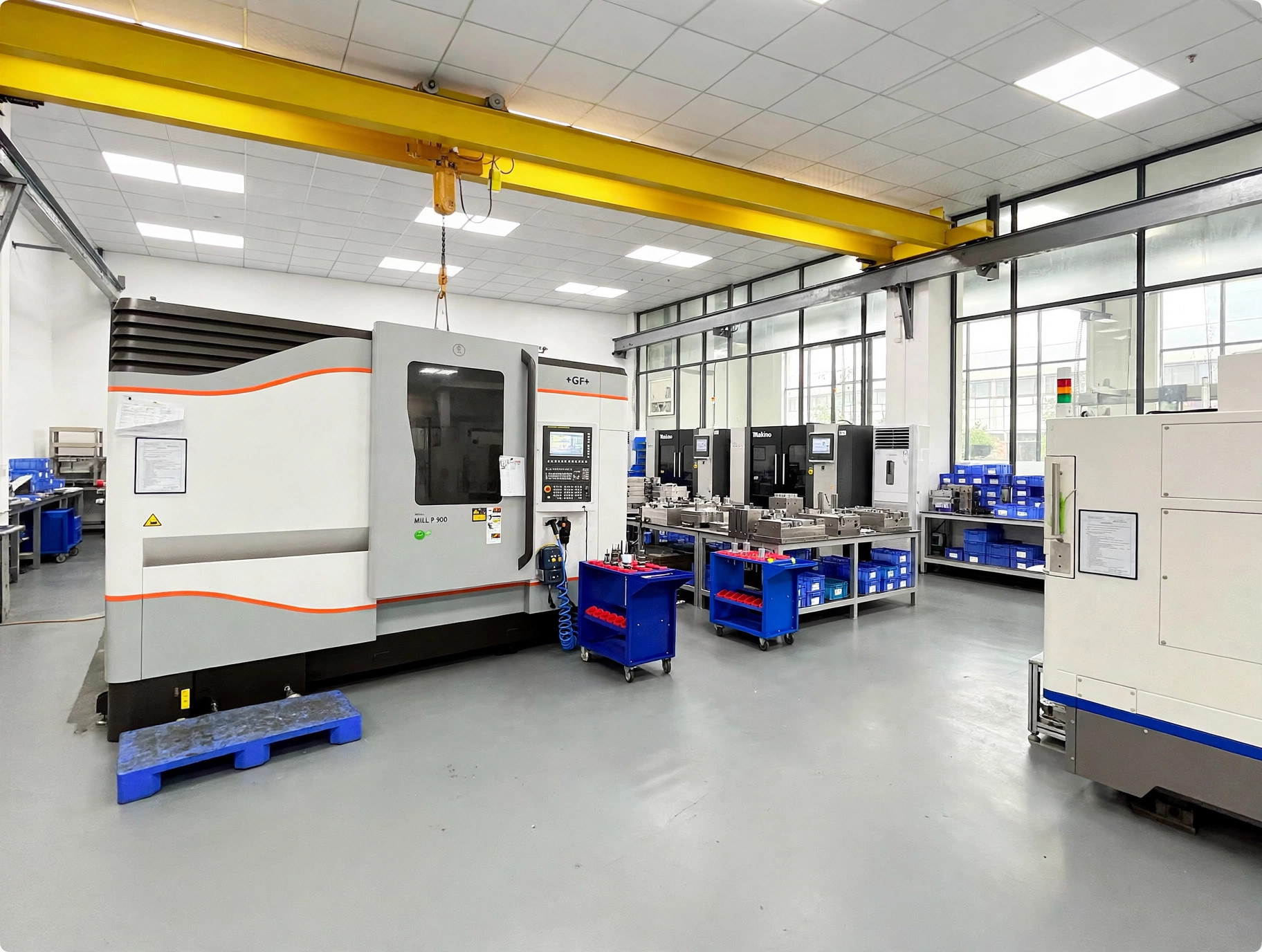
Makino machining centers in the WOKE Molds factory in Dongguan
Machining area in the WOKE Molds factory in Dongguan.

Before manufacturing: resolve drawing questions and approve the specification, commercial scope and acceptance basis. That release establishes what the physical manufacturing route must deliver.

Establish stock and holding references

Confirm material condition and suitable stock. Plan the initial holding and references for the functional diameters and axial features.

Machine the rotational features

Sequence the OD, ID, shoulders, grooves and threads with attention to support, tool access, edge requirements and dimensional relationships.

Complete the remaining operations

Review opposite-end work, parting-off and re-holding as needed. Carry the required references into secondary features and the agreed treatment sequence.

Inspect, protect and release

Verify the agreed characteristics in the defined final state. Complete the scoped records, identification and packaging for delivery.

Quotation and schedule

Make the RFQ comparable

Why do similar-looking shafts cost differently? Tool access, deep bores, grooves, usable thread length and support requirements can change the route. Re-clamping and the inspection of feature relationships also affect preparation and time.

PreparationProgramming, holding, special tooling and measurement preparation.
Part and batchStock yield, cutting time, quantity, treatment batches and acceptance scope.
ScheduleDrawing approval, material availability, route preparation, treatment, verification and transport.

Quote the trial lot, first production batch and expected repeat releases separately. A forecast helps planning; the size and timing of each actual release still influence purchasing and batch economics.

Repeat orders and delivery

Keep the next batch on the same basis

Confirm part number, drawing revision, material grade and condition, treatment, finish and acceptance requirements for each repeat release. A new material source, treatment route or specification change may need renewed approval.

For an ongoing program, agree which fixture, program and inspection records should remain available and how long they will be retained. State the intended release cadence and required lot identification so purchasing and receiving share the same baseline.

Protect functional ODs, threads, thin walls and bore entrances against contact damage. Review separation, corrosion protection where appropriate, and labels that connect the shipment to the agreed part revision and lot.

Practical answers

CNC turned parts questions

Start with the information available. Identify the critical requirements and the details that still need clarification.

Can you start from a 3D model alone?

Yes, a model can start the review. Add a drawing or explicit callouts for fits, threads, geometric controls, surface texture and acceptance details that the model does not define. Resolve missing requirements before production release.

Can I send metric or inch drawings?

Yes. Identify the intended units and keep the model, drawing and notes consistent. Any conversion, rounding or conflicting dimensions must be clarified during review.

Can you assess one prototype or a small first order?

Yes. Share the initial quantity and likely repeat demand. Stock purchasing, holding, tooling, treatment batches and inspection determine the feasible order scope and quotation.

Is there a fixed minimum order quantity?

The practical order quantity is reviewed with the part, material and manufacturing scope. Give the trial lot and repeat release quantities separately so the quotation reflects what you intend to purchase.

Can I request material certificates?

Yes. Specify the certificate type, material specification and required heat or lot traceability. Document availability and linkage to the supplied stock must be confirmed for the selected order.

Can you use customer-supplied stock?

Raise this at inquiry. Agree stock dimensions, condition, identification, documents and incoming acceptance, together with responsibility for unsuitable material, before it becomes an approved production input.

What part sizes and tolerances can you accept?

Send the complete geometry and feature-specific requirements. Feasibility depends on material, length and diameter, support, tool access, process sequence and measurement. The project review establishes the accepted scope.

Can you supply the part after heat treatment and finishing?

Include the required material condition, hardness, surface treatment and final dimensional requirements in the RFQ. The quotation confirms the compatible sequence, protected areas and final acceptance stage.

Can flats or cross-holes be included with the turned part?

Yes, include all features and their datum requirements in the drawing for route assessment. We confirm the secondary operations and the complete finished-component scope during project review.

How do you handle a legacy concentricity callout?

Provide the governing drawing standard and edition. We clarify the intended geometric control and evaluation before release; any revision to the requirement is agreed with your engineering team.

Can you review an urgent delivery date?

Yes. Send the required receiving date and destination with the drawing and quantity. Material, approval, preparation, treatments, inspection and transport must be checked before the schedule is confirmed.

Can you arrange international delivery?

EXW, FOB or DDP can be scoped by project. Share the destination and receiving requirements so packing, freight, duties and import responsibilities are explicit in the quotation.

Makino machining centers in the WOKE Molds factory in Dongguan

Start with your part

Discuss Your CNC Turning Project

Share your shaft, sleeve or threaded component and what it must do. Add the drawing, material, quantities and critical acceptance needs to begin a focused project review.

Have 3D models or 2D drawings? Email your files to peter@wokemolds.com.

Please review our Privacy Policy before sending project details.