
Micro Injection Molds
Custom injection molds for small plastic components and fine functional features. Bring critical geometry, reliable release and measurable acceptance into one tooling plan.
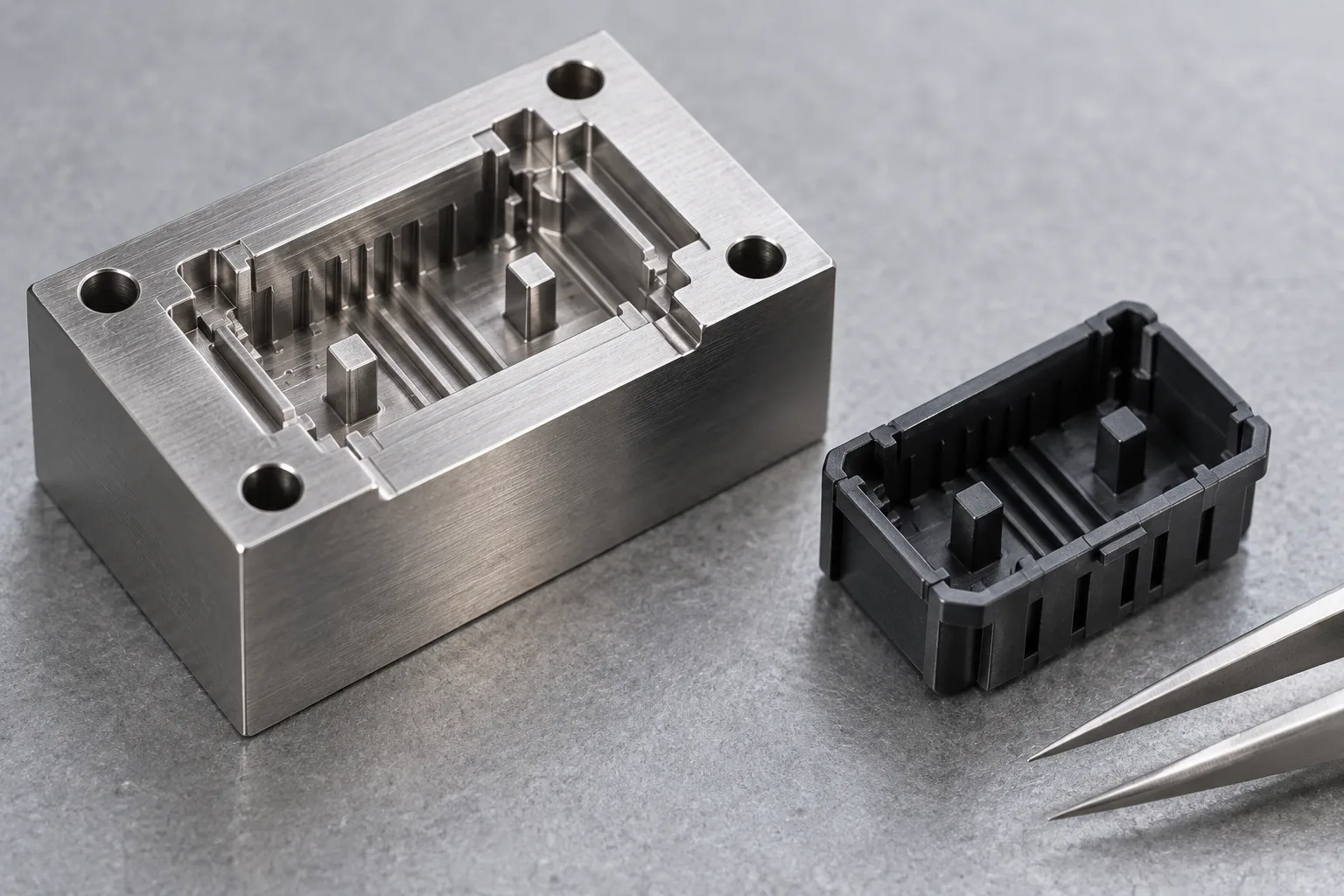
Small parts. Small features. Different tooling questions.
“Micro” can describe a tiny complete component, a larger component with a very small functional detail, a demanding tolerance, or a thin and difficult flow path. Those conditions can overlap, but they do not lead automatically to the same mold, runner, press or inspection plan.
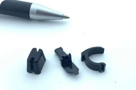
Control the whole path, not only the cavity
When the entire part is small, total shot including the runner, metering behavior, gate separation, ejection, static, containment and cavity identity may dominate the project. The useful output is a conforming part delivered to a defined collection point—not simply a filled cavity.
Small components from our company portfolio. Pen tip shown for visual scale.
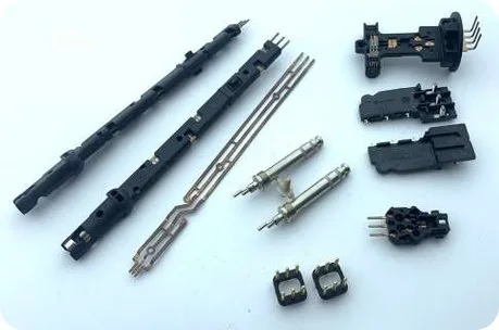
A larger part can still contain the decisive micro-risk
A connector housing, diagnostic component or mechanism may be easy to hold but difficult to reproduce at one slot, sealing edge, latch, bore or alignment interface. The mold review should begin at that feature and follow its fill route, surrounding steel, release direction and method of proof.
Connector components and contacts from our company portfolio.
No single cutoff replaces feasibility review. Part envelope, smallest functional feature, flow length and section, resin grade, gate and contact restrictions, tolerance, finish, volume and receiving equipment have to be considered together.
For the process background, review micro injection molding principles and applications alongside the part-specific tooling requirements.
Start with the feature that makes the part work.
Explore typical part functions and the tooling decisions they bring into focus.
Pin location, mating window and sealing edge
A narrow slot or bore may drive core support and fill direction. A thin shutoff edge may drive alignment and flash criteria. The gate witness, weld line and ejector contact must remain outside the electrical, optical, sealing or mating zone identified on the drawing.
Hot-part stiffness, undercut release and spring function
A clip can measure correctly at rest yet fail after ejection damage or conditioning. Review the flex arm root, local section, draft, support and release temperature, then define functional engagement or retention alongside dimensional checks.
Pivots, teeth, guides and contact surfaces
A tooth form or miniature guide needs complete replication without burr-like flash, damaged edges or excessive gate vestige. Steel access and replaceable insert boundaries should anticipate correction and wear rather than burying the critical geometry in a difficult repair.
One feature, three connected decisions.
Gate, vent, support and functional feature
Simplified section for engineering discussion
Get polymer to the detail without moving the defect into function
Gate position, runner volume, pressure loss and freeze-off influence whether the small feature fills. The review marks the acceptable gate witness, likely last-to-fill region and any functional area where a weld line is not acceptable. Venting must release trapped gas at the relevant end of fill without opening a path for unacceptable flash.
- Connect grade and flow behavior to feature section and path length.
- Review local temperature control where replication and stability need it.
- Treat vent and gate geometry as project-specific, not copied constants.
Protect the part and the steel when the mold opens
Slender cores, narrow blades and metal-on-metal shutoffs carry different risks. Core support, alignment, draft, pressure loading, steel choice and replaceability belong on a steel-risk map. On the part side, approved ejector or gripper contact zones should support release without bending a clip, marking a sealing face or losing a light part after ejection.
- Separate fragile core risk from sealing-edge and flash risk.
- Define support, ejection, handling and cavity separation where relevant.
- Make high-risk inserts serviceable where the architecture permits.
Prove the feature in the state in which it will be accepted
A nominal dimension is only useful when datum strategy, conditioning, cavity identity, access and method are defined. Flexible, reflective or hidden geometry may require a different approach from a robust accessible surface. Functional gaging or assembly can complement dimensions when it better represents the product requirement.
- Link each critical characteristic to a suitable method and fixture concept.
- Keep results connected to cavity, material condition, trial and revision.
- Agree which proof belongs at tool trial and which belongs on the receiving cell.
Match the resin and the injection unit.
Clamp tonnage does not describe the whole process. A mold that samples well should also have a credible route to repeat the part on the nominated production equipment.
Injection unit and screw, practical shot range, injection pressure and rate, nozzle interface, platen and locating details, ejector, cooling, hot-runner controls, dryer or temperature-control needs, removal access and process-monitoring interfaces.
- Start with the exact resin gradeFamilies such as POM, PA, PBT, PC and LCP present different flow, shrinkage, moisture and temperature requirements. Review the selected grade, filler and end-use condition together.
- Total shot includes runner and cushion behaviorFor a small part, runner choice can materially change shot utilization, metering control, residence time and material exposure.
- Filled polymers change the wear questionGlass or carbon reinforcement, high-temperature grades or corrosive constituents can influence steel, insert, surface and maintenance decisions.
- Production fit includes utilities and removalNozzle, mounting, ejection and cooling must fit, but so must part containment, cavity identity and any agreed automation or interface.
Agree how the feature will be measured.
The method has to see or reach the feature, resolve the tolerance with credible uncertainty, and hold the part without changing it. The quotation identifies the agreed measurement methods, fixtures and reports, including any specialist inspection that needs to be arranged.
| Characteristic | Acceptance basis to define | Potential method | Question to close before release |
|---|---|---|---|
| Accessible edge, bore or spacing | Drawing datum, conditioning time and cavity identity | Tactile, optical or multisensor measurement as suitable | Is the surface stiff and accessible, and is method resolution appropriate? |
| Small profile or sensitive surface | Profile definition, fixture orientation and surface criteria | Optical, microscopy or profile method | Will reflectivity, edge detection or fixturing bias the result? |
| Hidden channel or internal wall | Internal datum relationship and wall definition | Sectioning or CT through a confirmed provider/scope | Is nondestructive access required, and can the method demonstrate uncertainty? |
| Clip, engagement or alignment function | Representative mating part, conditioning and load/fit criterion | Functional gage, assembly or defined force/displacement check | Does standalone geometry predict the actual function? |
| Across-cavity consistency | Cavity-marked samples and agreed sampling plan | Selected dimensional and functional checks by cavity | Will pooled data conceal one cavity, insert or process difference? |
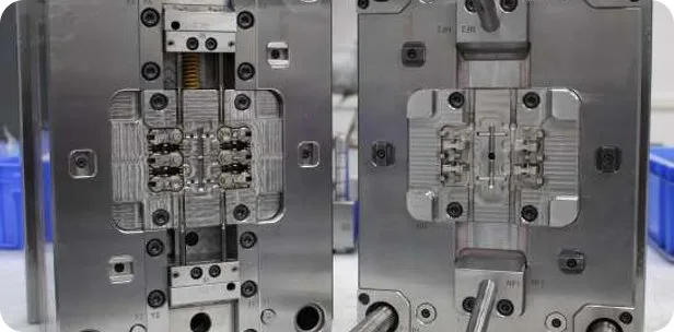
Serviceable tooling for critical details.
Where geometry and access allow, a high-risk core, blade, insert or shutoff can be separated for machining, correction or replacement. Formal DFM follows project kickoff; the released design records insert boundaries, material and specified component choices. During build, controlled issue updates and approval dependencies keep a change in the mold connected to the feature and its inspection plan.
Build a quotation around the critical feature.
Send the current 3D model and 2D drawing first. If available, add the marked functional feature, resin grade, expected demand, surface or flash limits and nominated production press. We can identify which remaining unknowns affect architecture, price, evidence or timing.
Choices that move cost and timing
- Runner, gate and cavity layout
- Balance material use, shot control, feature filling, separation and cavity evidence.
- Steel, inserts and treatment
- Match volume, grade, filler, wear, corrosion, repairability and approved supplier requirements.
- Inspection and functional proof
- Scope fixtures, external methods, cavity coverage, reports and representative mating checks.
- Receiving-cell integration
- Confirm fit, utilities, removal, controls and what must be demonstrated after transfer.
Define approval and handover together
- Trial and acceptance
- State representative resin, sample identification, characteristics, methods, visual limits, functional tests and approval responsibility.
- Customer dependencies
- Controlled files, approved material, timely design decisions, mating parts and receiving-machine data can change the critical path.
- Released support set
- Agree mold interface information, drawings, BOM or spares, maintenance guidance, inspection records and process data required for transfer.
- Commercial boundary
- Tooling, molding in our Shenzhen plant, modifications, external inspection and on-site support are included only where stated in the project quotation.
Micro Injection Mold FAQs
How small a feature can WOKE Molds mold?
We assess feature feasibility from your geometry and resin grade. Flow length, aspect ratio, surrounding steel, release, finish and the measurement method all affect what can be agreed. Send the drawing with critical features marked so we can define a project-specific requirement.
Can the tool run in our existing press?
Potentially, after comparing physical fit and injection capability. Share injection-unit, shot, nozzle, platen, ejector, utility and removal information; final proof on the nominated production cell should be defined in the acceptance scope.
How do you manage a fragile core or shutoff?
We distinguish a slender-core support problem from a sealing-edge and flash problem, then review alignment, draft, loading, material or treatment, access and whether the detail should be a serviceable insert.
Can gate and ejector marks be kept off a functional area?
Mark forbidden witness and contact zones on the drawing. Gate, parting, support, ejection and handling can then be reviewed together; the final solution also depends on fill and release feasibility.
Do you provide optical or CT inspection?
Where optical or CT inspection is appropriate, we confirm the provider, method, fixture and reporting scope for the project. Method resolution and uncertainty must be suitable for the actual feature and tolerance.
How are samples kept traceable by cavity?
Where cavity-level diagnosis matters, the trial plan can define cavity identity on the part or container and connect samples, measurements, material condition, trial settings and tool revision.
What changes if we switch resin grade?
Flow, shrinkage, conditioning, thermal exposure, wear and release can change. Review the new grade before approval and repeat the affected dimensional, visual or functional evidence.
What happens when the mold transfers to another plant?
Recheck mold fit, injection capability, utilities, auxiliaries and removal. Use released process and interface data to establish the new setup, then reverify the agreed part and process requirements on that cell.
Discuss Your Micro Mold
Share your part CAD and drawing, and mark the fine feature or functional interface that matters. Add the resin grade and receiving-press details when available.
Illustrative micro-feature tooling concept