
Projected area
The footprint of all parts and the runner seen from the mold opening direction, not the surface area. The calculator uses length × width × an outline factor, multiplies by cavities and adds the runner share.
Free engineering tool · Clamping force
Use this injection molding tonnage calculator to estimate the clamping force a mold needs before you ask for quotes. Enter the part size, cavity count, runner share, resin and wall thickness; the calculator applies projected area × cavity pressure × safety factor and shows the result in kN, metric tonnes and US tons.
The result is an early estimate for planning only. Final press size is confirmed in DFM from your 3D model, resin grade, gate layout and the receiving machine data.
All fields update the result instantly.
Estimate only. Check tie-bar spacing, mold height, opening stroke and shot size before choosing a machine.
Method
The melt pushes the mold halves apart with a force equal to cavity pressure acting on the projected area. The clamp must hold more than that force, so a safety factor is added. This is the same method explained in our clamping force calculation guide.
F (kN) = projected area (cm²) × cavity pressure (MPa) ÷ 10 × safety factor
The footprint of all parts and the runner seen from the mold opening direction, not the surface area. The calculator uses length × width × an outline factor, multiplies by cavities and adds the runner share.
The average pressure inside the cavity during filling and packing. It rises with stiffer resins, thinner walls and longer flow paths. The calculator sets it from resin group and wall thickness.
A margin of 10–20% covers process variation and pressure peaks. One metric tonne-force is 9.81 kN; one US ton is 0.907 metric tonnes.
Inputs
These are rule-of-thumb starting values for estimates. Mold flow simulation or trial data gives a better figure for thin-wall, long-flow or cosmetic parts.
| Resin group | Base pressure | Thick wall ×0.9 | Thin wall ×1.2 | Very thin ×1.4 |
|---|---|---|---|---|
| PP, PE | 28 MPa | 25 MPa | 34 MPa | 39 MPa |
| ABS, PS, PC/ABS, HIPS | 38 MPa | 34 MPa | 46 MPa | 53 MPa |
| PC, PA, POM, PBT, PMMA | 45 MPa | 41 MPa | 54 MPa | 63 MPa |
| Glass-filled grades, PPS, LCP, PEEK | 55 MPa | 50 MPa | 66 MPa | 77 MPa |
1 MPa = 10.2 kgf/cm² = 0.0725 US tons/in². Machine definitions and data sheets for injection molding machines follow EUROMAP recommendations.
Worked example
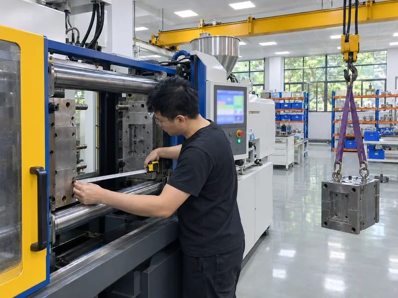
After the estimate
A mold often needs a larger press than its clamping force alone suggests. We confirm these points with your receiving machine data during DFM.
The mold width and height must pass between the tie bars and sit on the platens with clamping slots reachable.
Minimum and maximum mold height, plus enough opening stroke to eject the part and runner.
The shot weight should usually use about 20–80% of the barrel capacity for stable molding.
Sprue radius, locating ring diameter and ejector rod positions must match the press.
For mold design around your press, see our injection molding tool design guide and injection mold manufacturing service.
Buyer questions
Multiply the total projected area of all cavities and runners by the average cavity pressure, then add a safety factor of about 1.1–1.2. In metric units, kN = cm² × MPa ÷ 10; divide kN by 9.81 for metric tonnes.
Common rules of thumb are about 2–5 US tons per square inch of projected area, lower for easy-flow resins and thick walls, higher for thin walls and filled engineering resins.
No. Projected area is the part footprint seen from the mold opening direction. Side walls and ribs parallel to the opening direction add almost nothing.
Yes, a hot runner removes most of the runner's projected area, so the required force is lower than with a cold runner of the same layout.
Tie-bar spacing, mold height, opening stroke and shot size often need a larger machine than the clamping force alone.
It is a planning estimate based on typical cavity pressures. Final press size is confirmed in DFM, by mold flow simulation where justified, and at the mold trial.
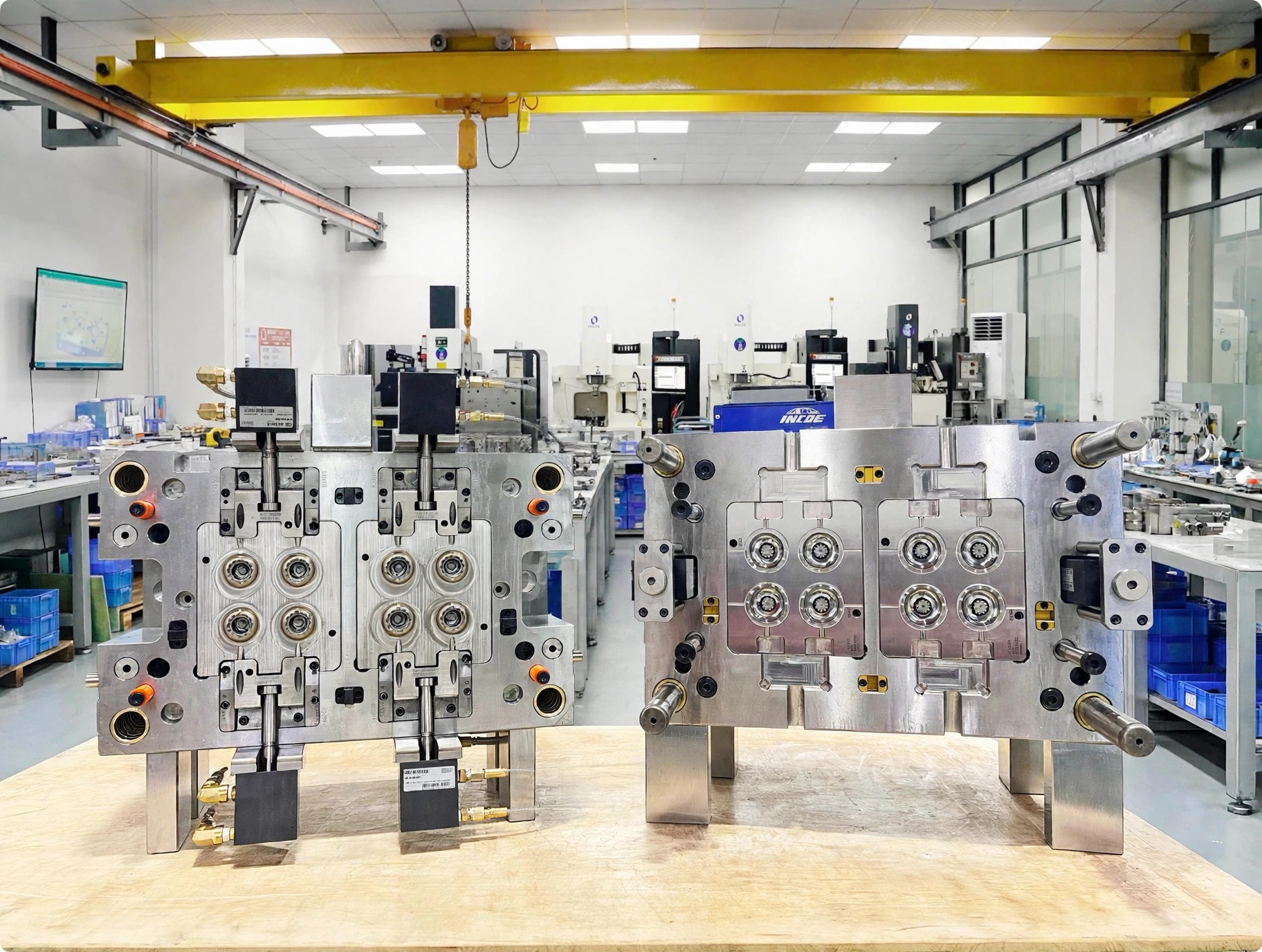
Share your 3D model and 2D drawing, then add the resin, expected demand, receiving machine, critical features and validation needs you already know.
Project review for injection tooling and press fit