
Two-Shot
Injection Molds
Two-shot tooling built around your part’s material regions, functional interface and receiving press.
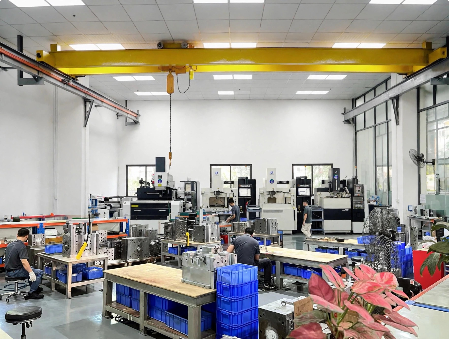
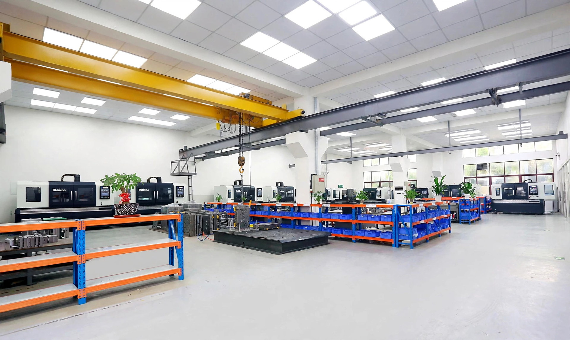
WOKE Molds designs, builds and trials two-shot molds in our own factory in Dongguan. We develop the tool around both material regions, first-shot retention and the receiving machine’s two-component sequence.
- Grade-level material review
- Tool and press interfaces aligned
- Validation tied to part function
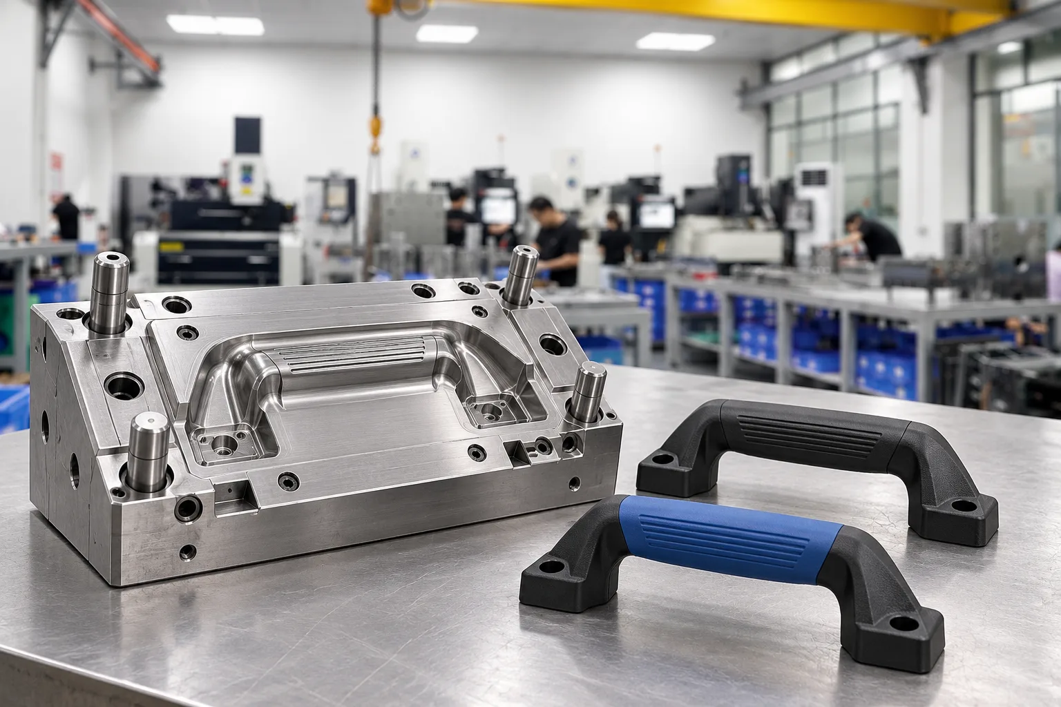
Choose the Manufacturing Route Before Freezing the Mold
Two-shot molding is useful when one finished part needs two colors, two material behaviors, or a defined interface produced in an integrated cycle. Typical goals include a rigid body with a soft-touch area, a sealing edge, contrasting controls or a functional surface. The manufacturing route should also fit demand, material condition and available equipment.
Overmolding describes one material formed over a substrate. It may be achieved in a two-shot tool or by loading a separately molded preform into another mold. We compare the integrated route with transfer or separately loaded preforms using actual geometry, demand, registration, handling and equipment constraints.
The mold can be supplied as a standalone tool. For molded-part production, define a separate volume, quality and delivery scope.
- Interface purposeIdentify whether the boundary provides grip, sealing, cushioning, color separation, insulation, capture or another function.
- Exact materialsProvide supplier and grade for both shots, including color carrier, filler, release package and approved alternatives.
- Critical surfacesMark cosmetic faces, texture, gloss, witness-line limits and areas where gate marks or flash are unacceptable.
- Production basisShare annual and lifetime demand, required finished parts per cycle, automation expectations and nominated molding site.
- Acceptance basisDefine dimensional, appearance and interface tests only where they relate to the part’s intended function.
First shot
The substrate fills, packs and cools enough to stay positioned without distortion, marking or premature release.
Index or transfer
The mold or retained preform changes station while preserving orientation, support and a workable surface-temperature window.
Second shot
The second material fills the controlled boundary, vents correctly and completes the same finished part.
Move the Preform—or Change the Cavity
The selected concept must retain and support the first shot, expose the right boundary to the second cavity, and remain serviceable within the intended machine. In a rotary layout, different stations can inject the first and second shots on different parts in parallel; the saleable output is the number of finished parts completed per cycle, not the sum of every station position.
Part shape, interface access, shot weights, station balance, thermal window, rotation envelope, automation and maintenance strategy are reviewed together. A concept that fits the geometry but cannot connect to the receiving press is not a complete tool specification.
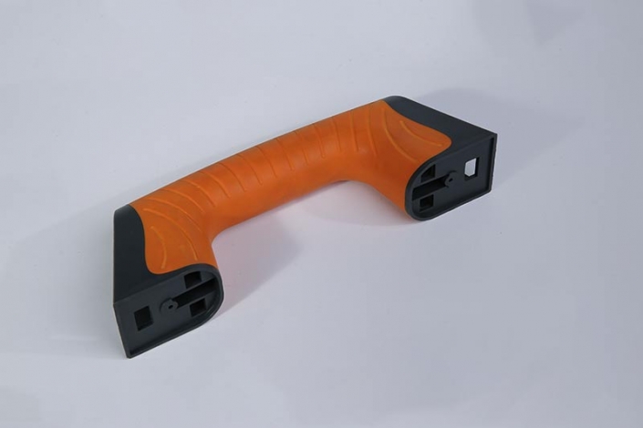
Tooling Concepts to Match Your Part
Select the movement around the material boundary, first-shot retention and available press functions.
| Architecture | What moves or changes | Engineering focus |
|---|---|---|
| Rotary platen / turntable | A mold half rotates between injection stations. | Station timing, indexing accuracy, mold-open and rotation envelope, utility routing and machine drive/control. |
| Index plate / rotating insert | An internal plate or carrier moves the retained first shot. | Preform support, carrier alignment, moving-tool complexity, ejector/core layout and service access. |
| Transfer | A robot or operator moves the preform to another cavity or machine. | Orientation, cooling time, contamination, registration, gripper design, sensing and automation interfaces. |
| Core-back | An internal movement opens volume for the second shot. | Suitable geometry, positive sequence, boundary sealing, actuation, controls and press signals. |
Material Pairing & Bonding
Bond performance depends on the exact grades, additives, color system, surface condition and processing window—not polymer family names alone. We review the pair against part loads, service conditions and the evidence needed for acceptance.
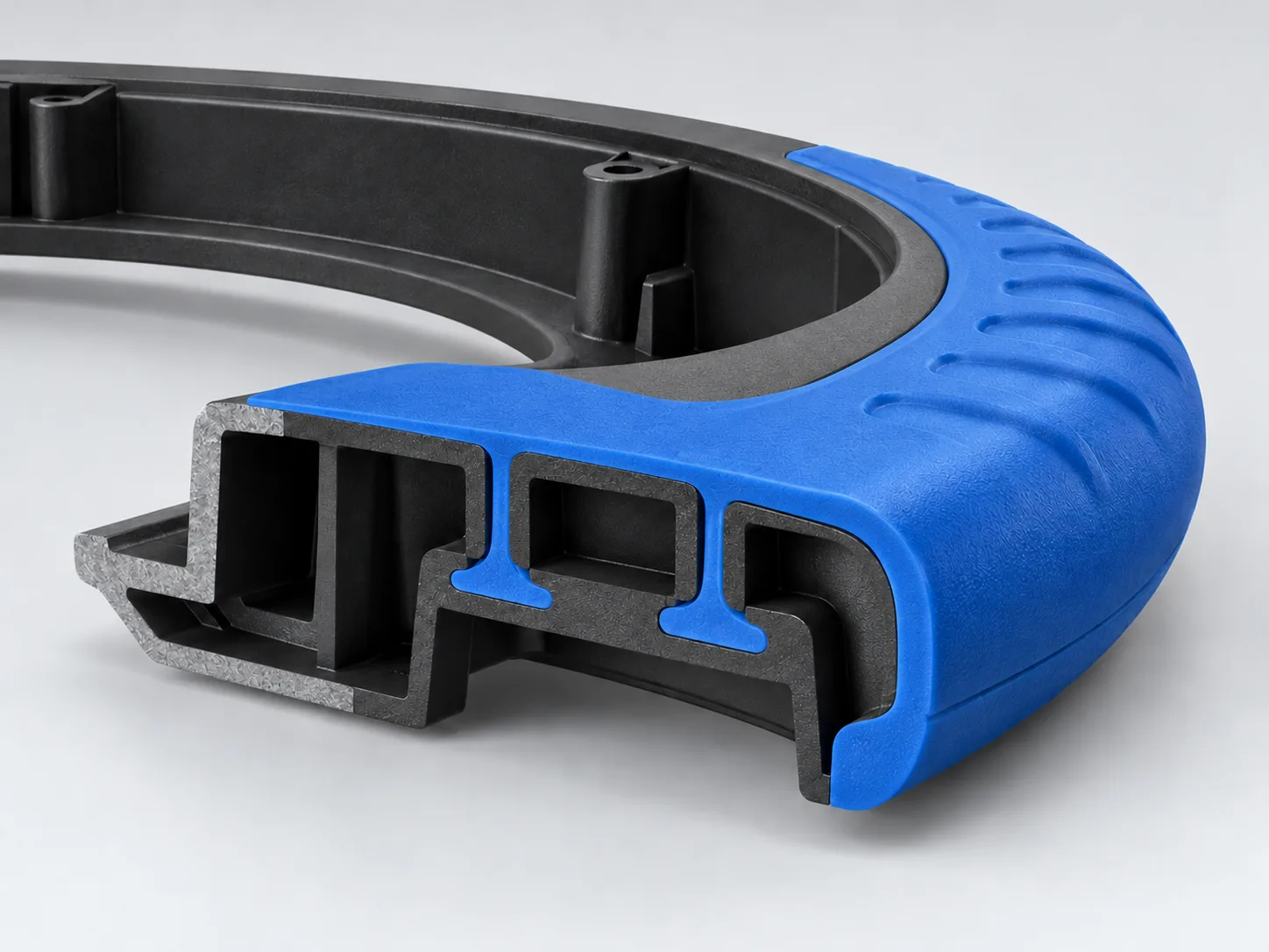
Review the pair as a working interface
- Grades and surfacesConfirm exact resin grades, additives, colorants and surface or preparation conditions with supplier data.
- Geometry and retentionAssess chemical or physical adhesion and, where needed, retention through holes, grooves, wraps or other captive features.
- End-use acceptanceDefine sealing, durability, appearance and agreed peel, pull, shear or environmental checks around the part’s actual duty.
Engineering controls that protect the boundary
Retention & support
Manage shrink direction, draft, core grip and cooling so the first shot remains located and supported.
Boundary & flow
Set shutoffs and vents for first-shot variation; position gates to reduce air traps, jetting, erosion, pressure demand and unwanted witness marks.
Thermal & shrinkage
Balance substrate temperature and strength for indexing and second-shot pressure; assess wall ratio, stiffness, packing, cooling and warpage.
Design the Mold for the Receiving Press
Match the tool to both injection units, nozzle positions, mounting and opening limits, rotation or transfer functions, utilities, controls, automation and safety sequence. The machine maker, model and current interface data provide the basis for that review before design release.
The process window couples first-shot cooling, index or transfer time, second-shot filling and packing, and final cooling. Parallel station work can support output only when the stages are balanced and the cell can execute the intended sequence reliably.
Feed and thermal control
Gate position, runner concept, nozzle reach, hot-runner zones, mold-temperature circuits and drying strategy are aligned to each material and shot.
Movement and support
Rotation or transfer needs defined drive ownership, positioning, envelope, load limits, first-shot support, ejector interaction and safe access.
Sequence and automation
Core pulls, valves, sensors, robot actions, reject handling and machine I/O must exchange the correct permissives and confirmations.
Receiving-machine data to confirm
- Injection-unit position and orientation
- Screw diameter, shot capacity, pressure and plasticizing rate per unit
- Nozzle radius, orifice and adjustability
- Platen, tie-bar and mounting pattern
- Mold height, daylight and opening stroke
- Ejector stroke, force and pattern
- Mold and rotation load limits
- Rotation axis, direction, angle, drive, envelope and positioning repeatability
- Core-pull and valve-gate circuits
- Temperature zones and utility maps
- Automation access and sequence I/O
- Material feeding, drying, coloring and parallel plasticizing/injection capability
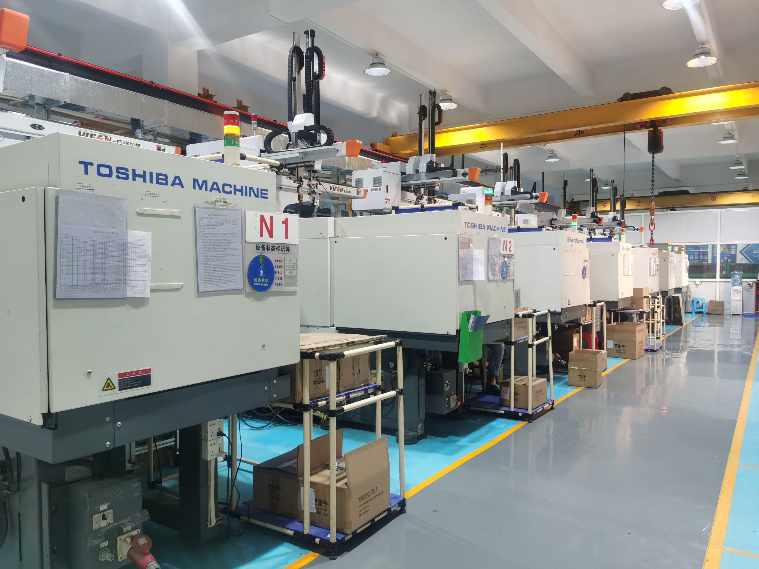
Our Dongguan factory has a Haitian 250 T two-shot trial press, and our Shenzhen plant runs 5 two-shot presses for series production.
Turn the Agreed Sequence into Trial Evidence
Available drawings, material grades, press data, volumes and acceptance needs inform feasibility and scope before quotation. Formal DFM begins after project kickoff and resolves the material boundary, retention, tooling details, press interfaces and open decisions.
The same engineers handle design, tool manufacture and trials, linking trial observations and corrections to the agreed revision.
-
Engineering release
Confirm tool architecture and construction, material inputs, machine interfaces and the acceptance plan against the approved project basis.
-
Manufacture and fitting
Machine, inspect and fit cores, cavities, carriers, shutoffs, movements, feed systems and the required service connections.
-
Tool trial
Run suitable equipment with agreed grades, recording sequence, retention, filling, appearance and relevant processing observations.
-
Correction and recheck
Document changes, repeat affected checks and assess whether the process window supports the defined part and acceptance requirements.
-
Approval and handover
Compile scoped samples, records, documents and operating interfaces for customer review, approval and shipment release.
Validation follows the part’s function
Agree the checks, test conditions and records needed to approve the part for its intended function.
- Dimensions + appearance
- Dimensions and datum scheme; appearance and boundary witness.
- Materials + trial revision
- Material and color traceability; trial conditions and revision.
- Functional tests
- Peel, pull or shear if agreed; leak or pressure testing for seals; environmental exposure if required.
- Open actions + approval
- Open actions and disposition recorded for customer review.
Compare a Defined Tooling Scope
Align the quotation, acceptance basis and receiving-team handover before release. Open assumptions and customer-supplied inputs are identified so changes affecting price or lead time can be reviewed.
Quotation scope
- Tool construction
- Architecture, steel, components, feed system, movements, controllers and scoped auxiliaries.
- Press & controls
- Receiving-machine interfaces, utilities, temperature control, automation expectations and customer-supplied data.
- Trial & acceptance
- Material and equipment basis, sample quantity, measurements, functional checks and acceptance responsibilities.
Handover package
- Documents & operating information
- Released files, interface and utility maps, component references, controller, trial and process information as agreed.
- Spares & maintenance
- Scoped spare and wear items, circuit identification, preservation, lifting, installation and maintenance information.
- Packing & delivery
- Packing, destination and EXW, FOB or DDP with the named place and responsibilities confirmed in the quotation.
Start with the inputs available: current part files, shot regions, material grades, requirements, demand, press data and interface tests. We will clarify gaps and the quotation basis.
Two-Shot Injection Mold FAQs
Practical answers for choosing, quoting and accepting an integrated two-material tool.
Is two-shot molding the same as overmolding?
No. Overmolding describes one material formed over a substrate. Two-shot molding describes an integrated sequence in which the same part receives two injections, usually with two injection units and an indexing or cavity-change function. An overmolded part may instead use a separately molded and loaded preform.
When should we consider separately loaded preforms?
That route can suit existing single-shot equipment, lower demand, large substrates or processes that benefit from separate stations. Compare handling, contamination, substrate temperature, registration, automation, tooling investment and annual volume. Two-shot reduces separate handling, but requires the mold and production cell to support the complete integrated sequence.
How is the tool architecture selected?
Selection follows how the first shot can be retained and presented, the accessible interface, material temperatures, shot volumes, station balance, press layout, automation and maintenance. Rotary and index concepts reposition the preform, transfer moves it externally, and core-back creates the second-shot volume through an internal mold movement.
Can any two plastics be bonded?
No. Compatibility is reviewed at exact grade level because adhesion modifiers, fillers, lubricants, color carriers, moisture and processing conditions affect the interface. Mechanical interlocks may supplement attachment where chemical or physical adhesion is weak or uncertain. The acceptance test should reproduce the relevant end-use load and conditioning.
What controls the time between shots?
The first shot must remain warm enough for the intended interface while becoming strong enough to survive opening, indexing, reclamping and second-shot pressure. Resin, wall thickness, mold temperatures, retention, movement time and station balance create a workable range; there is no universal delay suitable for every part.
Why is receiving-press data needed early?
A two-shot tool must physically and functionally match both injection units and the cell. Nozzle positions, shot capacity, platen and tie-bar envelope, mold height, opening and rotation space, drive, ejector, core circuits, utilities, controllers, robot access and safety I/O can all change the architecture.
How are flash and leakage risks addressed?
Boundary shutoffs must account for first-shot shrinkage, stiffness and process variation while still venting the advancing second material. Gate location, local support and packing pressure also matter. A clean-looking boundary does not prove a seal, so leak or pressure testing is specified separately when the part function requires it.
How should interface strength be validated?
Define the test around the part’s real load, with method, direction, speed, conditioning, units and failure mode. Depending on function, the plan may use peel, pull, shear, pressure or leakage checks, chemical exposure, thermal cycling or repeated use. The method and acceptance criteria are agreed for the project.
What is needed for an initial quotation?
Provide current 3D and 2D files, marked material regions, exact grades, critical and cosmetic boundaries, annual volume, receiving-machine data, automation needs and acceptance requirements. Service environment, customer tooling standards, approved material alternatives and existing supplier compatibility data help reduce major scope changes after kickoff.
When does formal DFM begin?
Available files, materials, equipment data, volume and acceptance needs support the initial feasibility and quotation scope. Formal DFM begins after project kickoff and documents the agreed part, mold architecture, machine interface, gates, cooling, first-shot retention, shutoffs, tolerances and validation risks that require customer decisions.
Discuss Your Two-Shot Mold
Send the part files and requirements you have. Material grades, marked shot regions and receiving-press data help us frame the tooling review.