
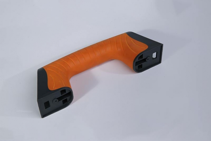
Grip and handling
Combine a load-bearing body with a tactile grip region on a handle, control or equipment housing.
Review focus: Grip coverage, hardness target, edge retention and exposure to oils or cleaning agents.
Two materials. One finished component.
Bring grip, sealing or a second color into your molded part. WOKE Molds builds two-shot molds in our Dongguan factory and runs the parts on two-shot presses in our Shenzhen molding plant.
Define the material interface, appearance boundary and acceptance requirements before committing to the production route.
Need a two-shot mold for your own press? Explore Two-Shot Injection Molds →
Start with the part's function
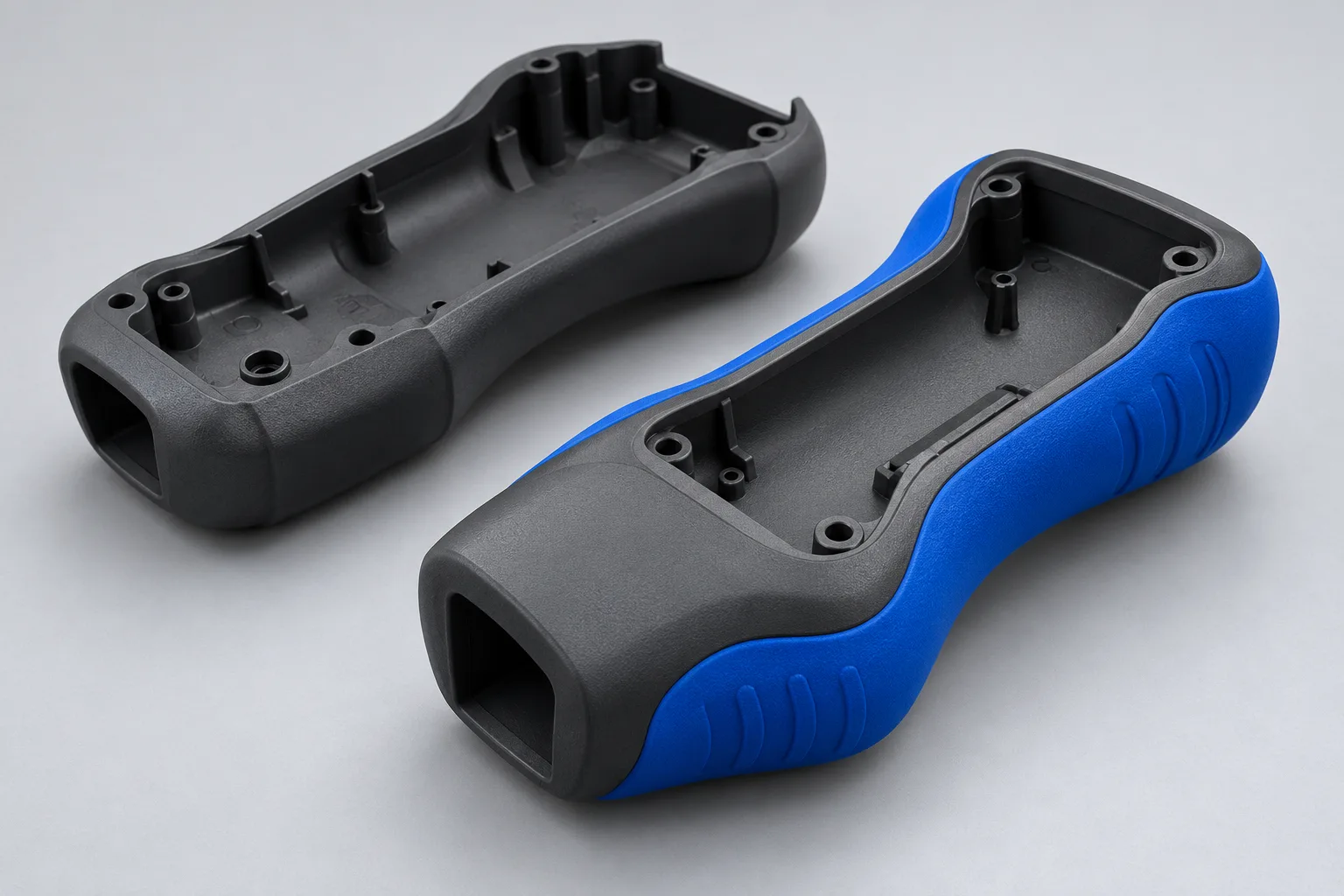
A second injection is useful when it creates a defined function or appearance that would otherwise need another component or operation. The part drawing should identify where each material belongs and what the interface must withstand.
Combine a load-bearing body with a tactile grip region on a handle, control or equipment housing.
Review focus: Grip coverage, hardness target, edge retention and exposure to oils or cleaning agents.
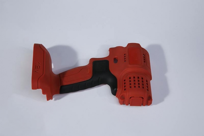
Bring a second material into selected housing surfaces while preserving mounting, assembly and ventilation features.
Review focus: First-shot support, shut-off geometry, gate witnesses and the permitted boundary variation.
A molded lip or perimeter feature can replace a separate seal in suitable designs. Compression, mating geometry, exposure and an agreed leak or functional test determine whether it works.
Two colors can define markings or separate visible zones. Specify the color reference, gloss, texture, boundary location and allowed mismatch; color alone does not establish material compatibility.
How two-shot molding works
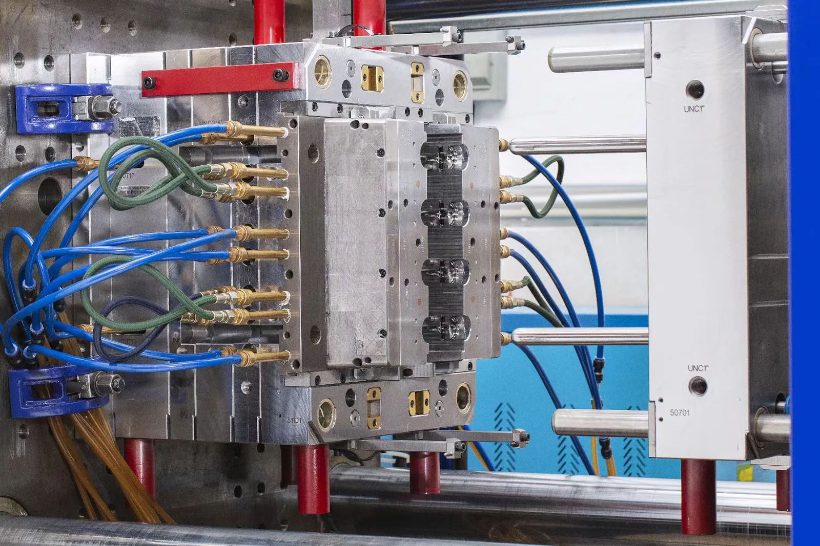
Two-shot injection molding, also called 2K or two-component molding, forms one component in two controlled injection stages. The first shot creates a substrate; the tool then moves the part or changes the cavity so the second material can be molded into the intended region.
Mold the first material to establish the structural shape, location features and the surfaces needed for the second stage.
Rotate, index or transfer the first shot, or change the cavity geometry. Keep the substrate located and supported against the next injection.
Inject the second material with a defined filling path, shut-off boundary and thermal history. Retention may use adhesion, geometry or both.
Release the combined part and inspect the agreed dimensions, visible boundaries and functional features. Both injection stages affect the finished result.
Choose the production route
Similar-looking components can be made by different routes. Compare the complete manufacturing and validation task: material behavior, registration, handling, design maturity, forecast and recurring part cost.
A dedicated multi-component cell controls the sequence between the two shots. It can consolidate handling and assembly where the part, materials and demand justify the tooling and equipment.
Controlled positioning and timing between stages, with a route designed around recurring production.
Tool complexity, first-shot support, cell configuration and the effect of either shot on total cycle and scrap.
Consider when the design is sufficiently stable and the combined part has a clear functional or recurring-production benefit.
The substrate is molded first and loaded into another mold or station for the second material. This can support a different tooling or production strategy, but the handling and surface history change.
Separate tools and operations can provide flexibility around substrate supply and production scheduling.
Storage, cleanliness, orientation, loading, temperature history and the way every substrate is located.
Compare when the substrate already exists, design changes are likely or a separate operation fits the program better.
Mold separate components and join them with a specified fastening, retention or assembly method. This retains a different set of material and service options.
Independent material choice, replacement or disassembly may be valuable for the product.
Additional parts, handling, joining operations, stack-up variation and the inspection of the assembled interface.
Compare when serviceability, reversibility or independently replaceable components matter more than integration.
There is no universal annual-volume threshold at which two-shot molding becomes the best choice. Compare tooling investment and recurring costs against the actual demand and acceptance plan.
These are engineering options, not a list of interchangeable machine features. The proposed tool and production cell must support the chosen route.
Rotates the moving tool side to the next station while retaining the first shot on its core. Review station alignment, retained geometry and the complete mold and machine interface.
Moves the first shot on a dedicated index element between cavity positions. Review the surfaces exposed to the second material, location and support through each movement.
A transfer device moves the first shot to the next cavity or station within the coordinated cell. Review gripping, orientation, timing and part support; this differs from storing and later reloading substrates.
A controlled tool movement creates space for the next material without transferring the part. Geometry must permit the new cavity and a reliable shut-off while the substrate remains supported.
Material pairing
A family label such as TPE or TPU is not a bonding specification. Evaluate both resin grades, the intended retention mechanism and the conditions the finished part will experience.
Manufacturer, grade, reinforcement, additives and color system.
Exact grade, hardness target, processing guidance and substrate recommendation.
Load direction, chemicals, moisture, temperature, aging and repeated use.
Adhesion, mechanical retention, appearance, seal or other functional requirement.
Does the specific overmolding grade support the substrate, color system and required hardness?
Are the interface, temperature window and final chemical or appearance requirements compatible?
Is the second grade specifically intended for the selected PP substrate and additives?
How will moisture, reinforcement and conditioning affect the substrate and interface?
Compatible chemistry and processing can develop adhesion at the interface. Supplier guidance, surface condition and the time and temperature history between shots all matter.
Through-features, wraps or other geometry can retain the second material. The design still needs suitable filling, release and load-bearing geometry; it does not prove sealing or adhesion.
Examples are starting points for grade-level review, not approved combinations or a stock material list. The process route and trial evidence determine the project decision.
Technical reference: Avient's grade-selection and processing guidance explains why material choice and processing conditions must be considered together. Grade-selection guidance and processing guidance.
Engineering the interface
After project kickoff, formal DFM connects the finished-part requirements to the mold concept. Review the first shot, second shot and their interface together rather than checking two independent plastic parts.
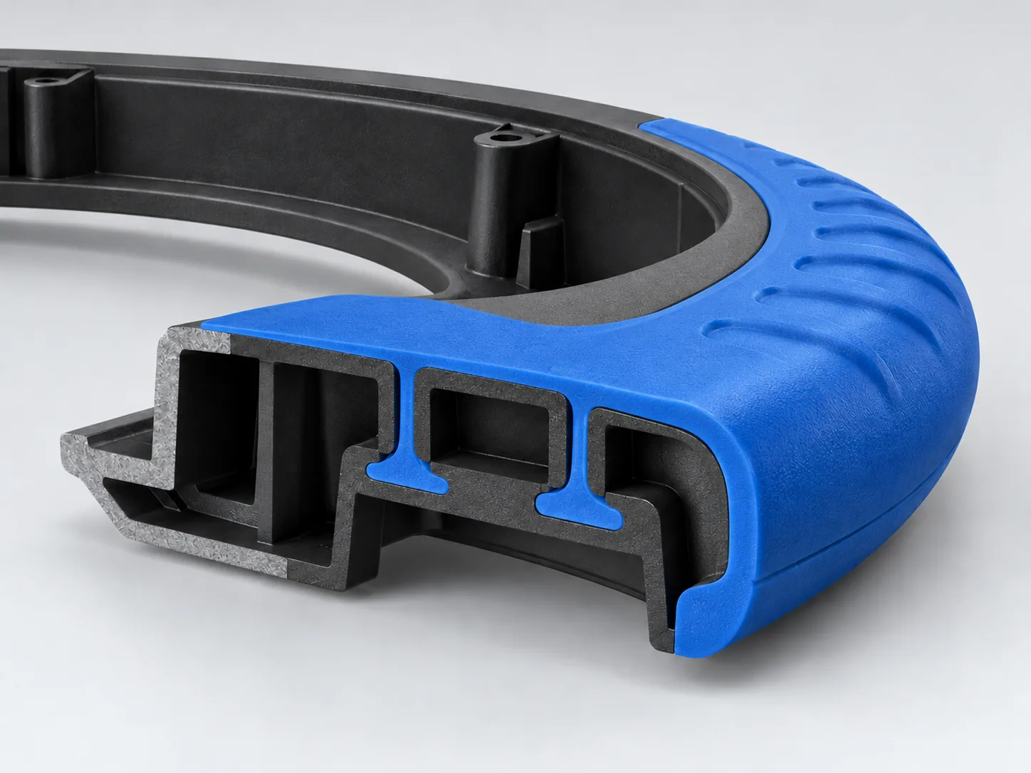
Identify the datums and contact areas that hold the substrate during the second injection. Check the risk of movement, crushing, distortion or breakthrough at thin and unsupported sections.
Specify the material boundary, allowable witness, flash limit, texture and gloss. Connect the tool shut-off to real substrate shrinkage and the surfaces allowed to carry contact pressure.
Review gates, weld-line locations, air escape and flow length around the interface. The second injection must reach its features without damaging the first shot or leaving unacceptable visible traces.
Assess how two materials and their different histories affect warpage, assembly datums and ejection. Define critical dimensions and measurement conditions on the finished part.
Mark the functional interface, visible surfaces and critical assembly datums on your drawing. Those three inputs make the engineering review more specific.
From symptom to review
A visible defect can have several causes. Trial review should connect the symptom to material, geometry, tool condition and the settings of both shots before choosing a correction.
Review grade compatibility, contamination, additives, thermal history, flow and the retention geometry. Agree how adhesion or retention will be tested, not only how the part looks.
Check the shut-off, substrate shrinkage, location, wear and injection conditions. Increasing clamp force alone does not establish the cause.
Review transfer registration, support, first-shot stiffness and the pressure or thermal load from the second shot. Use finished-part datums to locate the effect.
Review flow length, thin sections, gate freeze, air escape and material processing conditions. Check whether changes would create flash or damage elsewhere.
Separate color matching from material-edge variation. Review color-system control, carryover, gate witnesses, texture, gloss and the approved visual standard.
Review both materials, cooling and shrinkage, local thickness and interface constraint. Measure in the agreed conditioned state against the functional datum scheme.
From trial to recurring supply
A tool trial reveals whether the initial tool and process can produce candidate parts. Repeat supply also needs an agreed production basis: the intended cell, exact materials, critical parameters, inspection and the response to changes.
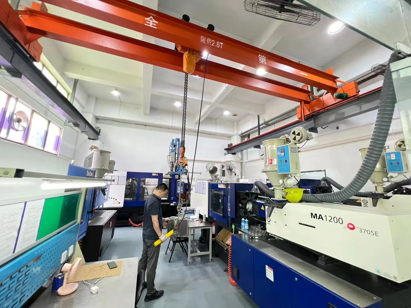
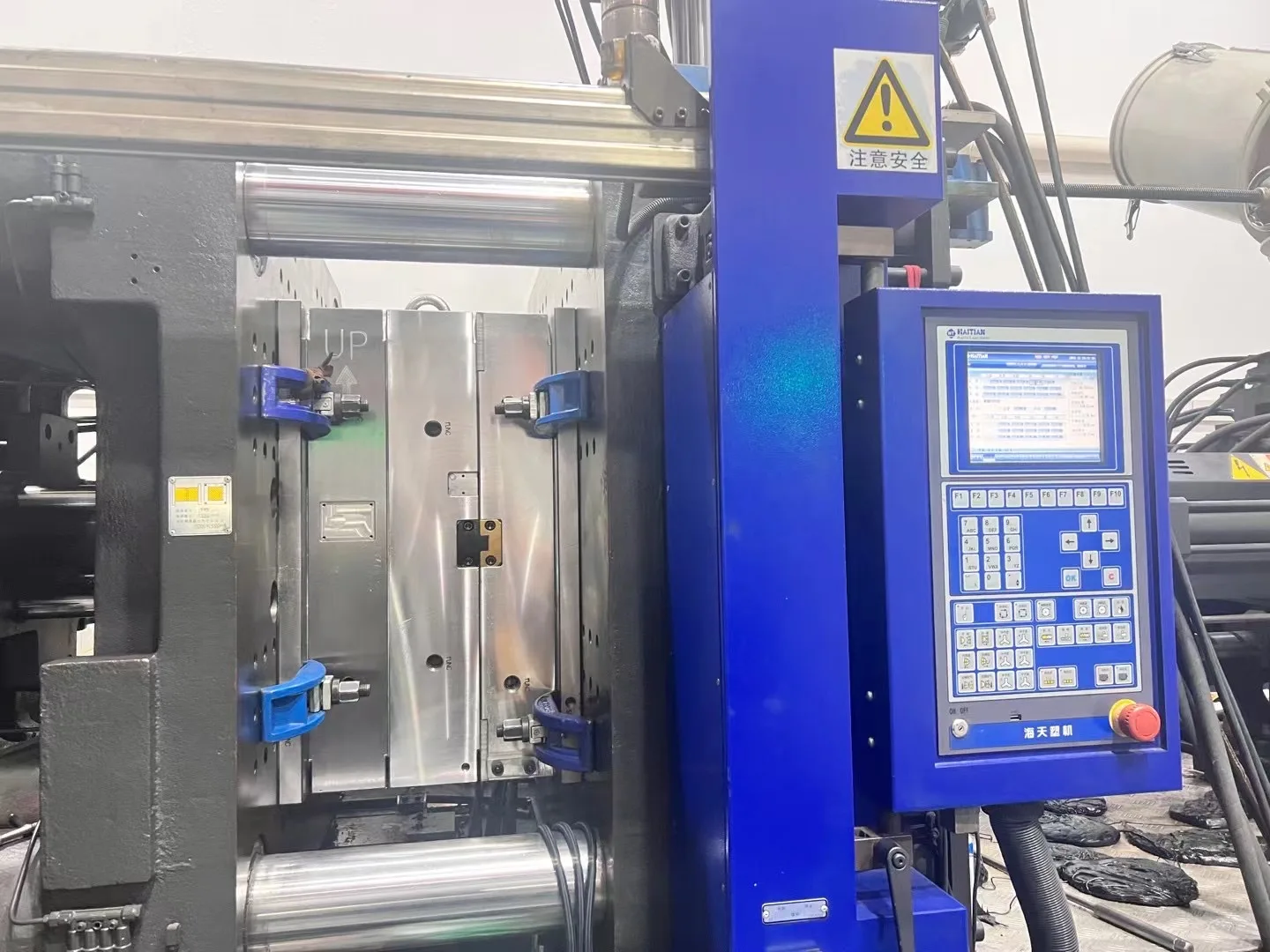
WOKE Molds builds the two-shot tooling, runs the trials and produces the parts. Our Dongguan factory has a Haitian 250 T two-shot trial press, and our Shenzhen plant runs five two-shot presses for series production.
Record the part revision, two resin grades, color references, tool condition and critical requirements. Review trial findings and approved corrections against that basis.
A defined sample and correction basis.
Compare dimensions, appearance and agreed interface or functional results. Identify which sample, drawing revision and inspection conditions define approval.
Agreed part-acceptance criteria and selected records.
Connect the intended cell to material preparation, transfer, injection and cooling controls for both shots. Specify any required production-run, capability or approval evidence in the project scope.
A production and inspection basis matched to the application.
Define lot identification, incoming and outgoing checks, packaging and release requirements. Agree the review needed for a resin, color, tool, process or production-site change.
A repeat-supply scope with change and delivery responsibilities.
Evidence that matches the function
Inspection can include first-piece, in-process and outgoing checks, critical-dimension measurement, appearance review and batch traceability. Select the checks and reports around the risks of this part, rather than assuming every two-shot project needs the same package.
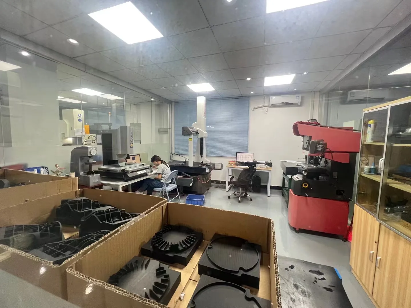
Define datums, critical features, conditioning, measurement method and sampling. Check the combined part and the dimensions most affected by transfer, shrinkage or distortion.
Use agreed color references and visible zones. Define the permitted edge variation, flash, gate witness, texture and gloss; a photograph alone is rarely a complete visual standard.
When required, agree a peel, pull, torque, leak, assembly or service-exposure test with its geometry, direction, conditioning and acceptance criterion. The test arrangement and report are part of the quoted scope.
Specify material records, inspection reports, trial records, traceability and any required FAI or PPAP elements. Additional studies and customer-specific documents are confirmed for the project.
For a soft TPE layer on a rigid substrate, ISO 813-2 describes a peel-test method. A material test or standard does not automatically prove the performance of a finished seal, grip or assembly. ISO 813-2 reference →
Quotation and delivery
A useful quotation states what is being made, how it will be accepted and the production assumptions behind the price. Tooling and recurring molded-part supply are defined as separate cost scopes.
Part and interface complexity, selected route, cavities, mold construction, engineering, trials, corrections and the agreed approval package shape the initial investment.
Exact resins and colors, part weight, cavity output, cycle assumptions, handling, inspection, secondary work, order quantities and packaging shape recurring part cost.
The quotation becomes more specific as the controlled files, material requirements and acceptance plan become clear.
3D model and 2D drawing, revision and any relevant mating parts.
Grade, manufacturer, color, hardness or other targets; identify what is still open.
Interface function, visible zones, dimensions and the required test or report scope.
Forecast, expected release quantities, destination, packaging and requested timing.
The quotation confirms the production route, tooling and part-supply scope, applicable schedule and delivery responsibilities. EXW, FOB or DDP terms can be quoted according to the project and destination.
Practical questions
Clear answers for material, route, approval and supply decisions.
Overmolding describes forming another material on a substrate. A two-shot cell coordinates two injection stages within a molding sequence; a reload route separately produces and loads the substrate. Both can make a multi-material component, but their tooling, handling, thermal history and validation requirements differ.
Yes, two-shot molding can create two-color parts as well as two-material parts. Exact grades, colorants, the material boundary and the processing route still require review. Using the same polymer family does not remove the need to verify appearance and interface performance.
No. Hardness difference describes a property, not compatibility. Bonding depends on the exact grades, additives, color system, surface condition, geometry and processing. Define whether the part relies on adhesion, mechanical retention or both, then agree the relevant verification.
No. A molded sealing region needs suitable compression, mating geometry, material behavior and dimensional control. Define the medium, pressure, temperature, exposure and test method. An integrated soft feature or a successful peel test does not by itself establish a waterproof rating.
No. Removing assembly or handling can create recurring savings, while the tool and production cell may require more investment. Compare the same part requirements, demand, accepted output, inspection, packaging and lifecycle assumptions across the routes. There is no universal break-even quantity.
Tolerance is assessed on the drawing, feature and material combination. Transfer location, shrinkage, warpage, interface geometry and measurement conditions affect the result. Mark critical dimensions and datums so the quotation and inspection plan can address the features that matter.
Send the available files and the functional targets, such as hardness, appearance, temperature or chemical exposure. Identify the open selections in the inquiry. Grade selection, interface verification and their effect on the proposed tool and production route can then be discussed as project requirements.
Not necessarily. Trial samples are a development milestone. Production approval may also need evidence from the intended materials, cell and operating conditions. Agree the dimensional, visual, functional and documentation requirements, including any specified production run or customer approval package.
Yes. A grade, additive or color-system change may affect flow, shrinkage, adhesion and appearance. Identify proposed changes before production and agree what needs review or revalidation. A previously approved family name does not automatically cover a new formulation.
Yes. Standalone two-shot mold development is a separate supply scope. Use our Two-Shot Injection Molds page when the mold will be installed and operated at your plant or nominated molder; the receiving press, tool interface and handover requirements then become central inputs.
Start with what you have
Share your part files and the function of each material. Add both grades, colors, forecast and acceptance needs when known. A clear interface requirement makes the next conversation more useful.