
Overmolding Molds
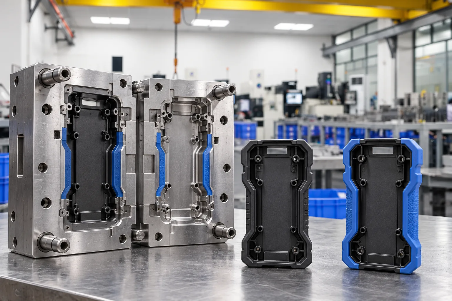
Custom overmolding molds for grips, sealing features and protective surfaces, engineered around your substrate, material pair and target press.
Tooling can cover the overmold stage alone or a matched substrate-and-overmold tool set. WOKE Molds designs, builds, trials and ships the molds from our own factory in Dongguan.
- 15+ years of team industry experience
- Our factory in Dongguan
- Engineering → trial → delivery
What should the overmold do?
Start with the function: grip, sealing or local protection. Each calls for a different material interface, substrate support and validation plan.
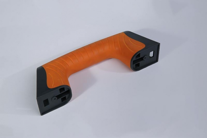
Grip and touch surfaces
A defined grip zone may need controlled edge location, texture, thickness transition and retention.
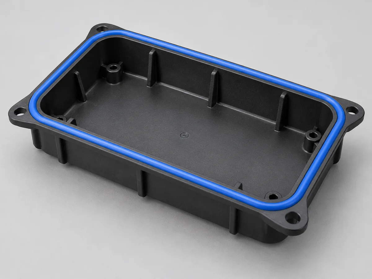
Integrated sealing features
Perimeter beads translate a local sealing requirement into mating geometry, compression targets, shutoff design and an agreed assembly test.
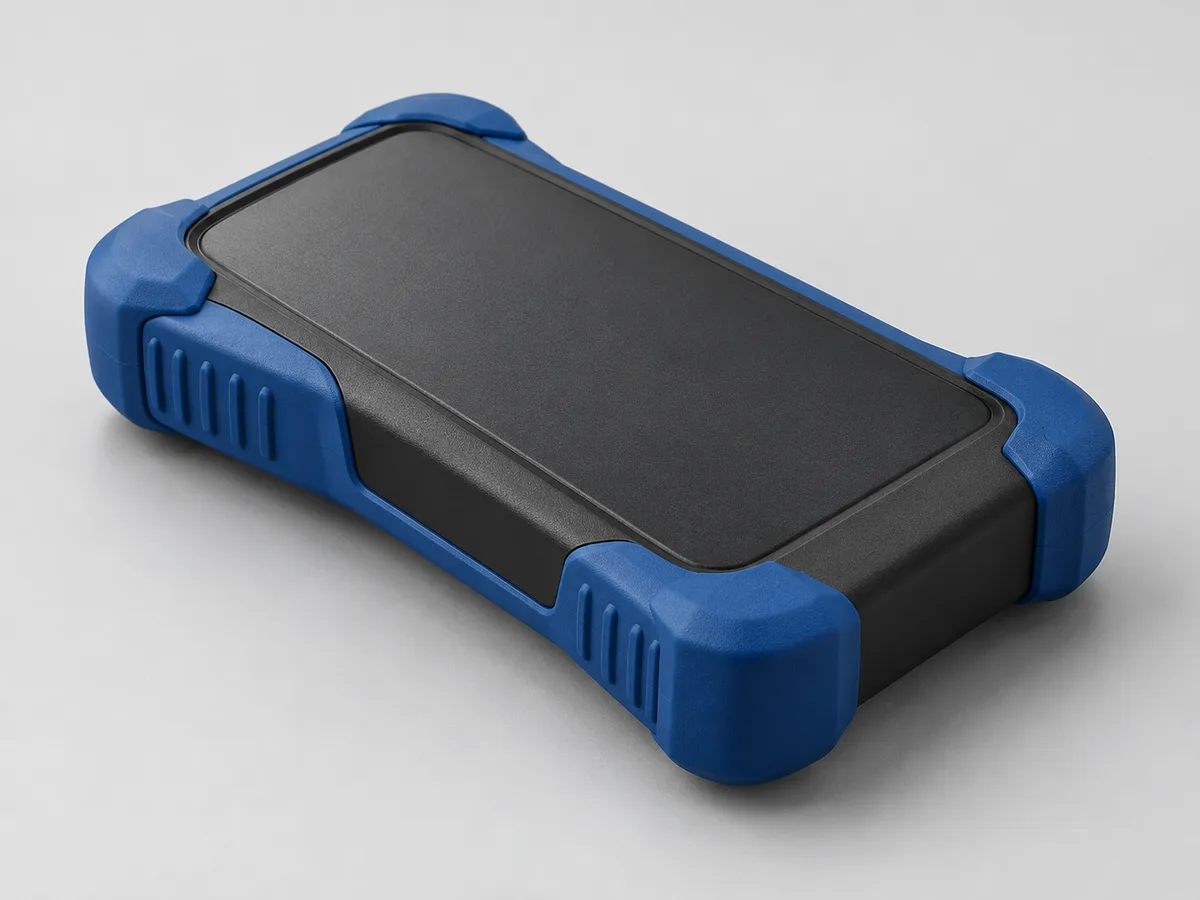
Protective overmolds
Corner or edge coverage can support impact or surface-protection goals when material, layer transition, adhesion and part-level validation are specified.
Tactile grip and appearance
A localized soft-touch or textured zone can improve handling and visual differentiation when its hardness, texture, edge position and cleaning environment are defined.
Integrated local features
A molded pad, bumper or gasket-like feature may reduce separate-part handling and assembly when the geometry, bond or retention route and service test support integration.
Protected contact surfaces
Selective coverage can cushion contact points or protect an enclosure surface when the expected load, wear zone and release geometry are translated into the tool.
Controlled functional boundary
A repeatable material edge can place grip, sealing or protection where the assembly needs it, provided the substrate variation, shutoff and inspection datum are controlled together.
Equipment controls
Grip, button surrounds and protected edges; review tactile zones and interface boundaries.
Handheld instruments
Touch surfaces and local protection; review handling loads, cleaning environment and substrate stiffness.
Appliance interfaces
Sealing beads and appearance zones; review mating parts, compression and visible witness limits.
Industrial housings
Protection and isolation features; review assembly datum, service exposure and end-use tests.
Choose the Right Overmolding Route
It can create tactile function, combine parts and add locally specified sealing, protection or appearance. Those outcomes depend on a grade-specific material pair, controllable substrate condition, suitable geometry and an acceptance method.
A preformed substrate may be reloaded into a separate overmold tool, or the substrate may be created within an integrated two-shot process. Insert molding usually captures a preformed component, often metal; the categories can overlap and are not mutually exclusive.
| Decision | Reload / separate tools | Integrated 2K route |
|---|---|---|
| Best considered when | Existing substrate, separate source, lower automation readiness or flexible handling is important. | Design and volumes justify an integrated cell and both shots can be controlled together. |
| Core review | Substrate variation, orientation, nesting, loading, contamination and handling. | Material sequence, mold architecture, index/rotation concept, press and controller fit. |
| Economic question | Separate tools and handling versus adaptable sourcing and simpler route changes. | Higher integration versus cycle consolidation and reduced interstage handling. |
| Next page | Insert injection molds for preformed-component tooling decisions. | Two-shot injection molds for integrated architecture. |
Control the substrate before the second material arrives
This is the recurring molding cycle, distinct from the tooling project milestones shown later.
Prepare
Condition and identify the approved substrate, grade and lot state.
Load
Orient, locate and support the substrate manually, by fixture or automation.
Fill
Close controlled shutoffs, then fill and vent the overmold region.
Cool and eject
Manage differential cooling, release and soft-material distortion.
Check
Inspect the interface, boundary and agreed dimensional or functional criteria.
Design the Nest Around the Supplied Substrate
Confirm the preform source and controlled revision, then review representative samples. Grade, additives, color, warpage, gate vestige and surface condition all affect how the substrate locates, seals and responds to the overmold shot.
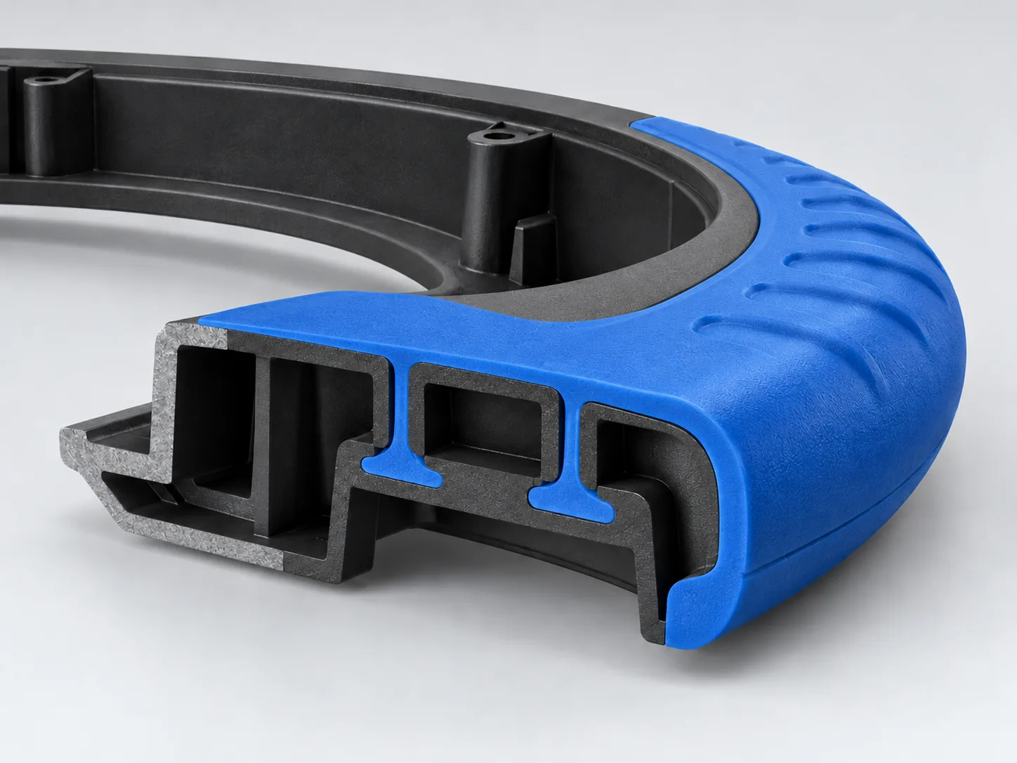
- DefinitionReleased 2D/3D data, material designation, critical datums and known variation.
- ConditionCleanliness, storage, moisture or aging history, surface handling and lot identification.
- LoadingOrientation, fixture access, poka-yoke, support faces and clearance for manual or automated transfer.
Qualify the Substrate and Overmold Material Pair
ABS, PC, PC-ABS, PA, PBT or PP substrates can be evaluated with TPE compounds, including suitable TPU grades where applicable. Bond behavior is established for the exact substrate formulation and matched overmold compound, including additives, colorants, surface state and processing history.
| Material starting point | What engineering needs to confirm | What trial evidence should resolve |
|---|---|---|
| ABS, PC or PC-ABS substrate | Exact grade, blend, additives, color, molded surface and a supplier-matched TPE compound. | Boundary fill, appearance, adhesion or retention and response to the expected service and cleaning conditions. |
| PA or PBT substrate | Exact grade and filler, drying/conditioning history, current dimensional state and the grade-specific overmold pair. | Fit in the nest, thermal response, interface performance and dimensions after the agreed conditioning state. |
| PP substrate | Substrate formulation, surface condition and a compound specifically matched to that formulation; review whether mechanical retention is needed. | Bond or retention under the defined load, with production-representative surfaces, colors and additives. |
| TPE compound, including suitable TPU grades | Required feel or hardness, service and cleaning exposure, flow and thermal window, surface finish, draft and release behavior. | Fill and venting, texture reproduction, ejection without tearing or sticking, and the defined functional test. |
Define the interface duty
State whether the interface resists peeling, carries a service load, locates a soft feature or supports tactile and appearance requirements.
Approve the exact formulation
Record both supplier grades plus relevant colorants, fillers and additives. A formulation or supplier change is reviewed for processing and interface impact before approval.
Use representative trials
Use coupons for early screening and representative parts for geometry and process confirmation. Define peel, pull or functional loading and record adhesive or cohesive failure where meaningful.
Through-holes, grooves and selective wraparound can add mechanical retention when they align with the real load path, can fill without trapping air and allow the part to release without tearing. Their dimensions and location must also preserve substrate strength and the visible material boundary.
Control Support, Flow and the Material Boundary
Substrate support
Nest on stable datums and support thin regions against heat and injection pressure; verify seating and post-mold distortion.
Shutoff and witness
Set steel conditions that contain flash without crushing the substrate; define allowed boundary and witness condition.
Layer transitions
Avoid abrupt, uncontrolled thickness changes; inspect edge location, sinks and visible transition quality.
Gate and flow
Place gates for balanced fill while managing shear, weld lines and sensitive appearance or bond zones.
Venting and release
Vent end-of-fill regions and coordinate draft, texture and ejection so a soft or tacky layer releases without tearing.
Cooling and dimensions
Account for two materials and substrate thermal history; measure agreed dimensions after defined conditioning.
Worked review: a perimeter sealing bead
The tool cannot be based only on the finished-part nominal surface. The substrate nest must locate from repeatable datums and accommodate the measured variation of the production preform without allowing injection pressure to shift or deform it. The bead edge then needs a shutoff on a stable surface, positioned so any permitted witness remains outside the functional compression path.
If retention geometry is required, it must fill and vent with the selected compound, remain supported during packing and release cleanly at ejection. The final check is made in the actual mating assembly: bead height alone does not establish sealing performance because substrate variation, mating-part tolerance and compression act together.
- Confirm the real substrate windowUse representative preforms to check datum seating, warpage, gate vestige and local support.
- Control the functional edgeLink shutoff location and witness limit to the mating surface and inspection datum.
- Validate the assemblyMeasure conditioned geometry, then apply the agreed compression and service test to the real mating stack.
The tool must fit the cell that will actually run it
Manual, fixture-assisted and robotic loading have different access, repeatability and sensing needs. The final quotation defines included loading jigs, sensors and cell responsibilities.
For a two-shot plant, rotation, index and dual-unit inputs are handled in the linked two-shot tooling review.
Engineering, Toolmaking and Clear Project Updates
WOKE Molds designs, machines, inspects and ships molds from our own factory in Dongguan, with series production available in our Shenzhen molding plant.
Team industry experience
Engineering and project support for material interfaces, mold architecture, tooling manufacture and trial decisions.
Our own factory
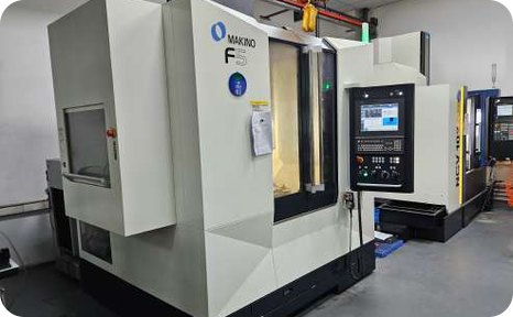
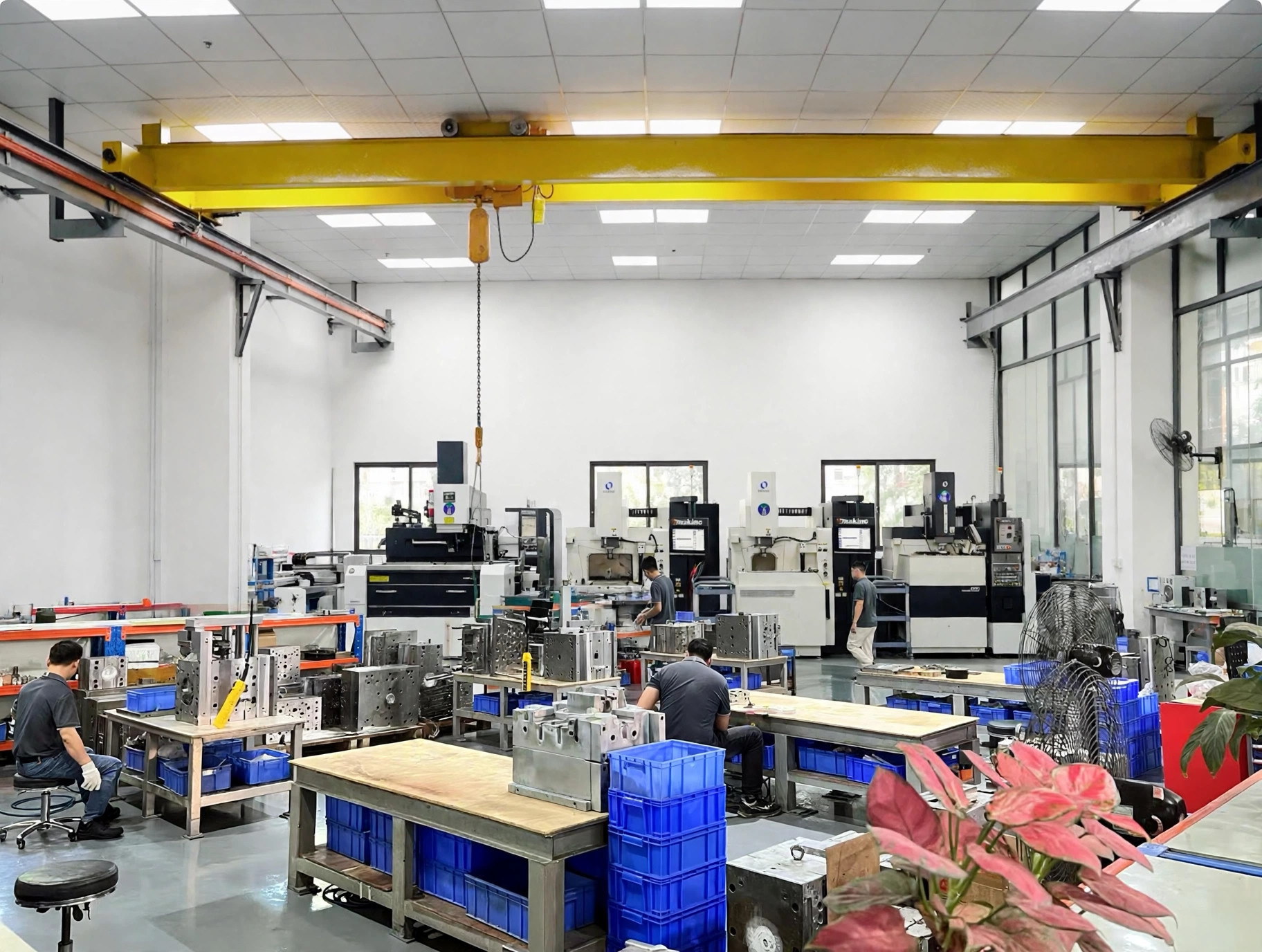
CNC, EDM, grinding, fitting, mold trial and CMM inspection support in Chang’an, Dongguan.
Defined before manufacture
Tooling can follow systems such as HASCO, Meusburger and DME, with specified components and receiving-plant interfaces confirmed in scope.
Released 2D and 3D mold drawings, weekly photo updates and key engineering data keep approvals and progress visible. Trial findings and corrections are tracked against the agreed part and tool acceptance criteria.
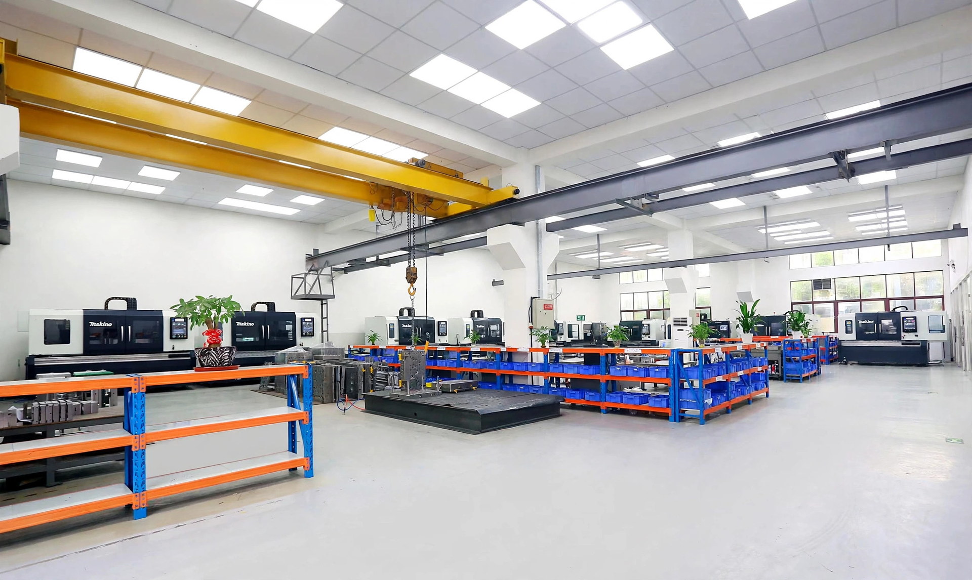
See the machining, fitting and inspection environment
Machining, mold fitting and dimensional inspection are part of the in-house tooling workflow shown here.

From Design Review to Tool Approval
Two prospective reviews show how requirements become validation
Typical review situations show how the requirement, tooling decision and validation plan connect.
Grip region: repeatable feel and retention
- Requirement
- Stable touch zone with an edge that does not lift under the agreed use load.
- Decision
- Confirm actual grade pair, grip thickness transition, gate direction and selective retention geometry.
- Validation
- Record visual boundary, representative handling and a defined peel or pull check when appropriate.
Protective housing: a durable retained boundary
- Requirement
- Corner and edge coverage must remain retained under the agreed handling and service conditions.
- Decision
- Select the compound and local layer transitions, then coordinate retained geometry, gate position and soft-material release.
- Validation
- Review representative handling, retention and service exposure, with impact or aging checks where the acceptance plan calls for them.
Validation for the Interface and Finished Assembly
Incoming steel, resin and supplied components can be checked against project requirements; machining, fitting and CMM checks support the tool build. The quotation identifies the inspection records and reports needed for the project.
| Requirement | Method | Evidence when agreed |
|---|---|---|
| Substrate datum and condition | Revision, grade/lot, seating, cleanliness and visible condition check. | Incoming record, photos or fixture confirmation. |
| Boundary, flash and finish | Defined visual limits and measurement at critical edges. | Trial photos and issue log. |
| Adhesion / retention | Defined peel, pull or functional loading; note adhesive/cohesive failure when useful. | Test record with material pair and method. |
| Dimensions | Measure named characteristics after specified conditioning. | FAI, full dimensional or CMM report as required. |
| Sealing function | Assembly compression and agreed aging, media or leak test only where specified. | Functional report against the specified end-use requirement. |
| Trial control | Record grades, settings, revisions and issue closure. | Mold trial, material and inspection reports as required. |
What Drives the Overmolding Tooling Cost?
The practical comparison includes the complete tooling and cell interface. Downstream handling and assembly are decision inputs even when they are outside the quoted tool price.
Tool set
Substrate tool status, overmold tool, cavities, nests and side actions.
Engineering level
Steel, cooling, texture, grade behavior and dimensional risk.
Cell interface
Runner, controller, loading fixture, sensing and receiving-press fit.
Validation
Material trials, representative substrates, inspection and functional testing.
Start with Your Substrate and Part Files
Share the available drawings and intended function. Known materials, demand and receiving-press information help us define the tooling route and identify any open decisions.
Inputs for a tooling quotation
- Part and substrate geometry
- Available 3D models and 2D drawings, including mating parts where sealing or assembly depends on them.
- Material and surface definition
- Supplier grades, colors, additives, substrate samples and any approved alternatives already known.
- Production context
- Demand, substrate source, loading concept, target press and receiving-plant standards.
- Acceptance priorities
- Critical dimensions, appearance, adhesion, handling or sealing requirements and relevant test conditions.
Scope to confirm before order
- Tool package
- Substrate and overmold stages, cavity count, nests, runner system and specified tool components.
- Production interfaces
- Included loading fixtures, sensing, utilities, controller connections and responsibility for cell integration.
- Trials and approval
- Representative substrates and grades, required inspection or functional tests, and the approval route.
- Handover and support
- Released documentation, agreed spares, preservation, packing and post-delivery support scope.
Timing is confirmed with the quotation. Typical mold lead time is 4–8 weeks, depending on complexity, steel and components, finish, material analysis, validation and customer approvals. EXW, FOB or DDP terms are agreed for the project.
Request a Tooling ReviewPrepare the tool for the receiving plant
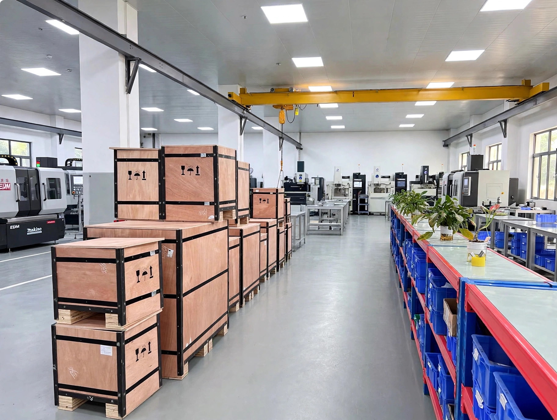
Handover can include released drawings, mold and utility interfaces, agreed trial and inspection records, spare-parts or maintenance scope and receiving-press information. Export molds are protected against rust, vacuum packed and secured in a wooden case for the quoted shipment route.
After delivery, support may include remote technical coordination and issue analysis. Modifications, spares, repair or on-site support are handled according to the project scope and the evidence available from the receiving cell.
Details that often affect an overmold RFQ
Can we supply the molded substrates?
Yes. Send the released drawing, exact grade, samples if available, expected variation and condition at loading so the nest and incoming checks can be planned.
Can a material grade be substituted after approval?
Approve any grade, formulation or supplier change through material and trial review because it may affect bonding, flow, color and the processing window.
Do colorants or fillers affect the interface?
They can. Identify the production formulation, because color, filler and other additives may affect flow, thermal response or adhesion.
Can manual loading be automated later?
Possibly, if access, orientation, datums, sensing and eject presentation are considered early. Retrofitting is a project-specific review.
How are aged or contaminated substrates handled?
Define storage, cleaning, moisture and surface-handling controls. Representative aged material may be needed for validation when that reflects production reality.
How should prototype adhesion results be used?
Use prototypes to screen candidate pairs and geometry. Confirm the selected route with production-representative grades, surfaces, part geometry and process conditions against the agreed test.
What must be defined for an overmolded seal?
Specify the mating assembly, compression range, tolerances, service media and test method. The assembled end-use validation establishes whether the seal meets the requirement.
Which mold standards can be used?
Tools can be designed around customer requirements and commonly used systems such as HASCO, Meusburger or DME. Brand and component requirements belong in the quotation.
What if our design files are incomplete?
Send what exists and state the intended function. We can identify which missing dimensions, interfaces or material facts prevent a reliable quotation.
When should we choose two-shot instead of reload overmolding?
Compare design maturity, volumes, substrate source, handling, quality control and available press architecture. See the two-shot mold page.
Can recurring part production be included?
It can be discussed, but it is scoped separately from export tooling, including material supply, cell, inspection, packaging and demand planning.
Can the tool be transferred to another production plant?
Transfer can be evaluated by comparing the approved trial cell with the destination press, utilities, controller, loading method and inspection requirements. Confirm any tool or process changes before production release.
Discuss Your Overmolding Tool
Send the substrate and finished-part files you have. Exact grades, intended function, demand and receiving-press information help us frame the tooling review.