Plastic mold manufacturer · Dongguan, China

Custom Injection Mold Manufacturing

Custom injection molds built around your part geometry, output target and press. As an injection mold manufacturer in Chang’an, Dongguan, WOKE Molds designs, machines, fits and trials every mold in our own factories, so the tool arrives maintainable and ready for your production.

Bring the files and production information you already have; open details can be resolved during project review.

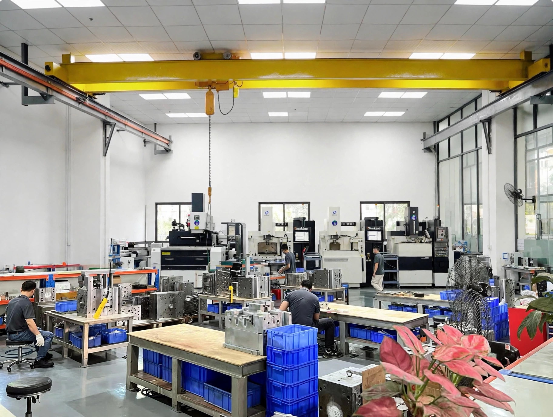
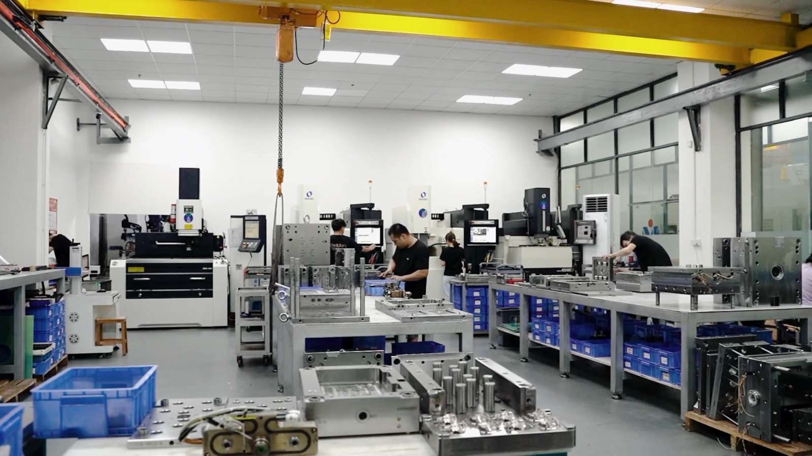
Plastic mold manufacturer workshop for custom injection molds at WOKE Molds
Engineering, build, trial and export handover by one in-house team.
  • 15+15+ years of team industry experience
  • 1,800 m²Factory floor in Chang’an, Dongguan
  • Engineering,Engineering, build, trial and delivery in our own factories
  • WeeklyWeekly photo updates during the build

Scope first

Choose the supply scope before choosing the mold details

The same part drawing can lead to two different purchases. An export-tool project ends with an accepted mold and handover package for another molding plant. A parts-production project continues into recurring molded-part supply. Keeping those scopes explicit changes the machine interface, validation location, documentation and commercial responsibilities.

Export mold

What you receive

The custom mold, agreed trial samples, specified records and handover items.

Decisions to lock

Receiving press, mold standard, electrical and water connections, runner controls, lifting and handling, destination, acceptance location, packing and spares.

Use this route when your own plant or nominated molder will run the tool.

Mold plus optional parts production

What you receive

The tooling scope plus a separately defined production scope for approved molded parts.

Decisions to lock

Production resin, forecast, release quantities, process approval, inspection frequency, packaging and replenishment terms in addition to the mold scope.

Use this route when you want the mold to go from trial straight into series production in our Shenzhen molding plant.

Prototype or bridge tool

Support design, material or process learning before a final production route is released.

Use it to learn from real molded parts before production investment is finalized. If steel, cooling, runner, cavity count, automation, surface or target press changes, define how that learning transfers into the production tool.

Production tool

Support repeat manufacturing against an agreed part, process and acceptance plan.

Define the expected service conditions, maintenance approach, cavity plan, runner, cooling, automation and validation evidence in the quotation so the tool is built around the intended production duty.

Export tool

Install and requalify the mold on a named customer or contract-molder press after the builder's trial and acceptance work.

Record target-machine fit, utilities, handling, process data and validation responsibilities early. Builder trial evidence then supports installation, setup translation and requalification on the receiving press.

Ongoing molded-part production is available under a separate scope with its own material, release, inspection, packaging and delivery requirements.

Part-led selection

Start with the part family and the reason the tool must be different

Mold architecture should answer a physical production problem. These recognizable component groups connect product geometry and function to the choices that usually drive the tool concept.

Housings, covers and bezels

Industrial controls, electronics, appliances and equipment enclosures.

Visible faces, sealing rims, clips, bosses and flat assembly datums make gate position, cooling, ejection and surface finish interdependent.

Conventional single- or multi-cavity tooling; slides or lifters for side features; two-shot or overmolding where a seal or soft interface is integrated.

Connectors and small precision components

Electrical interfaces, optical or electronic components and compact mechanisms.

Small features, pin protection, cavity-to-cavity consistency, venting, part handling and measurement method often drive the concept more than overall mold size.

Multi-cavity or micro tooling; insert molding when terminals, pins or other components are loaded before molding.

Threaded caps, fittings and adjustment parts

Closures, fluid or electrical fittings and products with functional internal or external threads.

The thread cannot always be released by straight ejection, so thread form, rotation, stroke, drive access and maintenance must be resolved together.

Conventional tooling for releasable threads; unscrewing architecture where a driven release is required.

Handles, rails and thick structural sections

Appliance handles, equipment grips, frames and structural arms.

A thick section may be needed for grip or stiffness but can concentrate material and create packing, sink or cooling challenges.

A conventional cored or ribbed design first; gas-assisted tooling when the geometry and receiving cell support a controlled internal channel.

Parts built around metal or a second material

Threaded inserts, terminals, seals, grips and multi-material interfaces.

Insert location, material bonding, shutoff, sequence, loading method and witness limits determine whether the interface can be molded repeatedly.

Insert molding, overmolding or two-shot tooling, sometimes combined with multi-cavity construction.

Architecture selector

Select the architecture that solves the production task

These are overlapping tool architectures, not mutually exclusive catalog models. A project can be multi-cavity and insert-loaded, or combine overmolding with an unscrewing feature. Conventional single- or multi-cavity tooling remains the base route when no specialty mechanism or material sequence adds useful value.

Best fit

When repeat demand justifies producing several matched parts per cycle and the resin, part geometry and press can support balanced filling and cooling.

Inputs to define

Annual and lifetime demand, family versus identical parts, shot size, projected area, runner concept, cavity spacing, critical dimensions and cavity-level reporting needs.

Trade-off

More cavities can improve output per cycle, but increase tool size, runner and thermal balancing work, upfront tooling and the effect of a cavity-specific issue.

Explore Multi-Cavity Injection Molds

Best fit

When two materials or colors must be molded in a controlled sequence and the target two-shot machine can index, rotate or transfer the part as the concept requires.

Inputs to define

Exact material pair, interface geometry, sequence, orientation, bonding requirement, first-shot support, machine platen and injection-unit arrangement, and acceptable witness areas.

Trade-off

Integration can remove handling or assembly, but ties the mold more closely to a compatible machine and makes interface, timing and material approval more demanding.

Explore Two-Shot Injection Molds

Best fit

When a metal, terminal, pin, bushing or other prepared component must be located and encapsulated during molding.

Inputs to define

Insert drawing and variation, loading orientation, retention, shutoff, flash limits, preheating if required, manual or automated loading assumption and pull-out or torque requirement.

Trade-off

The molded interface can consolidate assembly, but insert supply, orientation, loading time, protection and misload detection become part of production quality.

Explore Insert Injection Molds

Best fit

When a molded or prepared substrate receives a second material for grip, sealing, protection or an integrated interface.

Inputs to define

Substrate condition and tolerances, material compatibility, interface and mechanical locks, loading datum, sealing shutoffs, sequence, cosmetic boundary and functional test.

Trade-off

It can eliminate a separate attachment step, but substrate variation, handling and sealing surfaces can drive flash, shift or adhesion failures.

Explore Overmolding Molds

Best fit

When a functional thread or helical feature cannot be released reliably by straight ejection or a simpler collapsible or split concept.

Inputs to define

Thread profile, pitch, turns, release direction, molded material, shrinkage, torque, cycle sequence, drive source, access and lubrication or service expectations.

Trade-off

Driven release protects the thread form, but adds mechanism, sequence time, wear points and maintenance access to the tool.

Explore Unscrewing Injection Molds

Best fit

When very small parts or fine functional features make gating, venting, handling and measurement dominant design decisions.

Inputs to define

Feature geometry, exact resin grade, shot and runner ratio, gate removal, ejection and capture method, contamination sensitivity, datum strategy and measurement capability.

Trade-off

A smaller part does not mean a simpler tool; material residence, venting, fragile features, part loss and inspection can carry more project risk than the mold envelope.

Explore Micro Injection Molds

Best fit

When a continuous thick section may benefit from controlled internal gas for a hollow core or extended packing influence and a compatible production cell is available.

Inputs to define

Section path, resin, visible faces, gas entry and end condition, residual-wall and load requirements, controller and nitrogen interfaces, press signals and trial cell.

Trade-off

It may reduce solid material in a heavy route or improve its surface response, but adds channel validation, auxiliary equipment and machine-interface dependencies.

Explore Gas-Assisted Injection Molds

Tool definition

Define the tool around lifetime, process and receiving-machine needs

The quotation turns product information into explicit tool decisions, matching steel, runner, components and interfaces to the part and production environment.

Cavity and layout

Engineering inputs

Demand, press capacity, projected area, shot size, part stability, cavity-to-cavity requirements and maintenance strategy.

Defined output

Cavity count, family or identical layout, parting direction, side actions, ejection and service access.

Hot or cold runner

Engineering inputs

Exact resin grade, part and cold-runner weight, cavity and drop layout, gate position and wall, process and mold temperatures, color-change frequency, allowed vestige, annual demand, press and controller interface, automation and maintenance resources.

Defined output

A named cold-runner or hot-runner concept, gate arrangement, material-handling assumption, start-up and purging considerations, controller interface, spare strategy and responsibility for proprietary components.

Mold steel and wear strategy

Engineering inputs

Component role, exact resin and additives, lifetime demand, abrasive wear, corrosive or humid exposure, molding temperature, polish or texture, toughness, section size, repair or weldability, heat-treatment route, target hardness and local service conditions.

Defined output

A qualified prehardened, through-hardening or corrosion-resistant family and delivery condition for mold base, cavity, core, inserts and wear components, with named grade equivalence, hardness and certificates only where required by scope.

Component and mold standard

Engineering inputs

Receiving plant preference, spare availability, local service, connector practice and named brand requirements.

Defined output

Mold-base and component standard, branded or qualified-alternative policy, water and electrical connections, locating ring, sprue or nozzle interface and lifting provisions.

Surface and appearance

Engineering inputs

Visible faces, gloss or texture target, release behavior, weld-line and gate limits, resin and any coating or treatment need.

Defined output

Polish, texture or treatment specification tied to a defined face and an agreed approval method.

Machine fit

Engineering inputs

Platen and tie-bar space, clamping and opening requirements, daylight and ejector pattern, injection unit, nozzle, hot-runner zones, utilities, robot access and local safety provisions.

Defined output

A recorded receiving-machine interface used for design review, trial comparison and handover.

Choose the runner around material flow, recurring production and maintenance

Runner choice should connect the exact resin and gating layout with recurring handling, controls and the receiving plant's maintenance capability.

Route Choose when Practical benefit Tool and production consequences
Cold runner Runner removal and agreed scrap or permitted-regrind route are acceptable; demand supports a simpler system; and frequent material or color changes favor easier cleanout. Mechanically straightforward distribution, direct access for troubleshooting and fewer heated control elements in the tool. Each cycle produces a runner that needs separation and a defined scrap or approved-regrind route. Runner fill, cooling and ejection add material and cycle load, and gate removal may require handling or automation.
Hot runner Recurring demand, runner mass, gate placement or automated part handling justify a heated distribution system, and the receiving plant can support its controller, start-up, purging, spares and preventive maintenance. Delivers melt to each drop without a cold runner, creating opportunities to reduce recurring runner handling and place gates where the part and cavity layout require them. Adds heated zones, wiring, controls, thermal balance and proprietary service parts. Exact resin grade, temperatures, color changes, cavity/drop layout and gate details shape start-up, residence-time, maintenance and troubleshooting needs.
Hybrid or project-specific layout Only selected gates or cavity groups benefit from hot distribution, or the part family needs a combination of heated delivery and cold sub-runners. Can focus hot-runner complexity where it creates the most useful gating or material-handling advantage. Retains some cold-runner material and handling while adding heated-system interfaces. Balance, residence, gate freeze, service access and the responsibility split require explicit review.

Match the steel family to the component and service condition

Plastic resin serves the finished part's mechanical, thermal, chemical, regulatory and appearance needs. Tool steel serves wear, corrosion, temperature, polish, expected life and repair. Surface texture, polish, coating or treatment serves appearance, release or tool protection. A glass-filled resin, for example, can change wear protection and gate direction while still leaving several viable steel and finish routes to compare.

Steel family Choose when Practical benefit Design and manufacturing consequences
Prehardened A mold base, holder, structural plate, large section or moderate-wear cavity application benefits from a supplied hardness and a shorter route after machining. Can reduce or avoid post-machining hardening and simplify scheduling for suitable component roles. Available hardness sets the wear and polish envelope. Heavy abrasive demand, fine long-life cavity features or local high-load areas may need inserts, treatments or another family; confirm delivery condition and repair approach.
Through-hardening Cavity, core or wear components need higher hardness, compressive strength, wear resistance or polishability for the defined resin, features and production duty. Supports demanding molding surfaces and wear zones when grade, heat treatment and finishing are specified as one route. Heat treatment adds lead time and dimensional-change planning. Stock allowance, section size, toughness, grinding, final fitting, polishing and repair method must be designed around the chosen grade and target hardness.
Corrosion-resistant Corrosive plastics or additives, humid storage, condensation, aggressive cooling-water exposure, clean operation or a stainless mold package make corrosion control a primary requirement. Protects cavity, core or structural surfaces and can reduce corrosion-related finish and maintenance problems in the specified environment. Wear, toughness, polishability, thermal behavior and machinability still need evaluation. Select the family by component role and service exposure, then define delivery condition, heat treatment and compatible maintenance practices.

Whole-project comparison

Compare tooling routes across the full project

A lower upfront tool can be the right decision for modest demand or a stable simple part. A more integrated architecture can be justified when it removes recurring material, cycle, handling or assembly work. The quote should expose those differences without assuming savings before trial data exists.

Decision Simpler conventional route More integrated or specialty route What to compare
Upfront tooling Fewer mechanisms, interfaces or cavities can reduce design and build scope. Additional cavities, material stages, driven actions, inserts or gas provisions add engineering and build work. Released tool scope, bought-out components, controller or auxiliary equipment, trials and included corrections.
Lifetime and maintenance Fewer moving or proprietary elements may simplify service. Replaceable wear details or advanced mechanisms may protect function but need planned access, spares and trained maintenance. Expected shots, abrasive or corrosive resin, wear points, local spare availability and maintenance intervals.
Cycle and output A single-cavity or manual route may be adequate for lower demand. More cavities or integrated operations may increase output or remove handling, but only if filling, cooling, loading and release remain stable. Accepted cycle definition, uptime assumptions, cavity utilization, loading time and downstream bottlenecks.
Material use A cold runner or solid section may be acceptable where material cost and regrind rules allow it. Hot runners or gas-assisted sections may reduce recurring runner or core material, but require more equipment and process control. Part and runner mass, approved regrind policy, purge and color-change impact, overflow or trim and material price.
Validation A simpler part and tool may need fewer interface checks. Multi-material, micro, cavity-intensive or gas-assisted tools need additional interface, cavity, hidden-feature or cell checks. Critical dimensions, appearance, function, material identity, cavity traceability and receiving-cell confirmation.
Assembly Separate molded pieces or secondary operations may keep tooling flexible. Two-shot, overmolding or insert molding may consolidate assembly but moves responsibility into the mold and loading process. Avoided components and labor versus insert/substrate control, bonding, misload prevention, scrap containment and repair.

Engineering into steel

Turn the approved part intent into a buildable, maintainable mold

After kickoff, the engineering review connects part function to the provisions that will be cut into steel. Each input leads to a defined design output, approval point or manufacturing action.

Technicians fitting and assembling a custom injection mold
01

Review part function and lock the design basis

Starts with

Controlled 3D and 2D files, resin, mating parts, critical dimensions, visible faces, functional loads, production target, receiving machine and validation expectations.

Formal DFM reviews draft, wall transitions, parting, undercuts, shutoffs, gate and runner, venting, cooling, ejection, steel, tolerance risk and manufacturability. Moldflow is added when project complexity or customer requirements make defined fill, pack, cooling or warpage questions worth investigating.

Related design guides explain injection mold components, mold cooling and draft-angle considerations for the project review.

Output: Recorded assumptions, recommended updates, open decisions and an approved part and mold basis before detailed release.

02

Engineer provisions that can be manufactured and serviced

Starts with

Approved layout, selected steel, component standards, runner choice, surface requirements and machine interface.

Define cavity and core inserts, shutoffs, slides or lifters, cooling circuits, vents, gates, runners, ejection, wear plates, replaceable details, sensors or connections where specified, and safe access for fitting and maintenance.

Output: Released 2D and 3D mold drawings, component order basis and manufacturing data.

03

Machine, fit and finish the released design

Starts with

Released manufacturing data and checked steel and components.

Our toolmakers handle CNC machining, sinker EDM, wire EDM, grinding, drilling, fitting, polish or texture preparation, assembly and inspection. Process selection follows the feature: milling establishes accessible geometry, EDM forms features that cutting tools cannot reach efficiently, wire EDM controls through profiles, grinding establishes mating or datum surfaces, and fitting resolves real shutoff and movement relationships.

Output: An assembled mold whose critical steel, interfaces, movements, water paths and finish are ready for trial.

04

Control changes through trial feedback

Starts with

Trial conditions, molded samples, dimensional, appearance and functional findings, and tool observations.

Separate tool corrections from part-design, material and process changes; agree the action; update affected drawings or records; then verify the revised condition.

Output: An approved update history and evidence tied to the accepted tool condition.

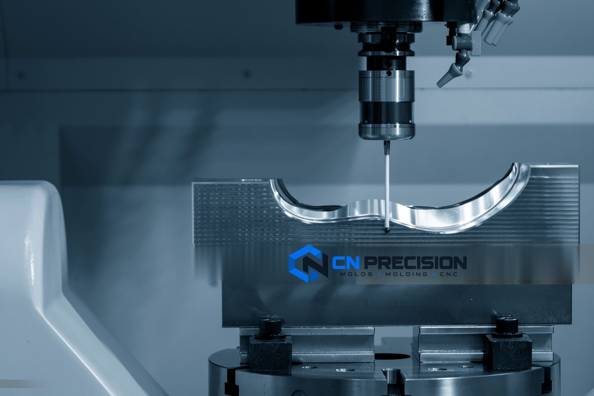
Precision measurement of an injection mold cavity
Inspection is tied to the agreed critical features, tool condition and trial basis.

Evidence chain

Build quality evidence from incoming steel to the accepted trial part

Inspection follows the features that determine whether the mold can run, whether the part meets its drawing and whether the accepted condition can be identified later. The project selects the reports needed for approval and transfer.

  1. Steel, base and bought-out components

    Confirm specified grade, condition, dimensions and component identity where required. Record certificates, branded-component evidence or supplier documentation only when included in the scope.

  2. Machined and fitted mold

    Inspect critical cavity, core, insert and interface features; check shutoffs, moving actions, ejector travel, water circuits, connections, assembly and selected finish requirements before trial.

  3. Trial setup

    Record the mold version, resin, machine, key process assumptions, cavity identification and relevant auxiliary equipment so results are not separated from their conditions.

  4. Trial parts

    Evaluate agreed critical dimensions, appearance zones and functional or assembly checks. For multi-cavity tools, retain cavity identity where cavity-level comparison matters.

  5. Conditional report package

    Select the evidence the project needs: inspection report, full dimensional or CMM report, material certificate or COA, mold-trial record, FAI, PPAP elements, control documents or corrective-action records. The quotation names the selected package.

Acceptance criteria, sample quantity, measuring method, appearance standard, functional test and approval responsibility should be agreed before the final trial.

From RFQ to handover

Keep assumptions, approvals and corrections visible from RFQ to receiving plant

  1. 1

    Files and quotation basis

    WOKE Molds reviews the available 3D and 2D files, identifies the requested deliverable, records known resin, demand, machine, standard, finish and validation inputs, and lists open assumptions in the quotation.

  2. 2

    Kickoff, formal DFM and design approval

    After project kickoff, the team reviews part function and manufacturability, agrees required part updates, develops the mold concept and obtains the defined approvals before steel release.

  3. 3

    Build with weekly photo updates

    Steel and components are prepared, the mold is machined, fitted, finished and assembled, and customers receive weekly photo updates and key engineering data against the project schedule.

  4. 4

    Trial, feedback and correction

    The assembled mold is trialed on suitable equipment using the agreed basis. Samples and tool behavior are reviewed, actions are agreed, and approved corrections are implemented and rechecked.

  5. 5

    Acceptance and export handover

    The accepted condition is tied to the agreed inspection and trial evidence. The mold is finally inspected, protected, packed and shipped with the scoped records and any quoted spare or wear items.

  6. 6

    Receiving-machine fit

    The receiving plant installs and recommissions the mold against the recorded press and utility interface. Machine-independent process conditions and machine-specific settings are kept distinct where the project records them. Trial-cell differences become defined setup-translation and requalification actions.

ScheduleTypical mold lead time is 4–8 weeks. The applicable schedule depends on complexity, steel and component availability, hot-runner or specialty systems, texture or surface work, approval timing and validation scope, and is confirmed in the quotation.

Trade termsEXW, FOB or DDP can be quoted according to project and destination. The quotation defines the selected term, responsibilities and included costs.

Quote preparation

A useful mold quotation starts with the part files

Send the 3D model and 2D drawing first. They establish geometry, datums, interfaces and revision control. Unknown commercial or production details can be recorded for follow-up instead of blocking the first review.

  • Start here3D model and 2D drawing with revision
  • Then defineMold only, parts production only, or both as separate scopes
  • If knownExact resin grade, color, filler and approved substitution rules
  • If knownAnnual and lifetime demand, expected order pattern and target cycle or output basis
  • If knownReceiving machine, mold and component standard, hot-runner preference, connectors and utilities
  • If knownCritical dimensions, visible faces, texture or polish, assembly and functional requirements
  • If knownValidation and documentation package, destination, requested timing and trade term

Buyer questions

Plastic Mold Manufacturer FAQs

Do I need to choose one of the seven mold types before asking for a quote?

Send the part and production information first. The seven types describe engineering architectures that can overlap. A conventional tool may be sufficient, or the project may combine multi-cavity, insert, overmolding or another feature where the part requires it.

How is the cavity count selected?

Cavity count is reviewed against demand, shot size, projected area, press fit, runner balance, cooling, part stability, cavity-level quality needs, tool investment and maintenance. The selected count balances useful output with stable operation and lifetime service needs.

Should my mold use a hot runner or a cold runner?

A cold runner can be simpler to operate and maintain, while a hot runner can reduce recurring runner material and support some gating layouts. Resin sensitivity, gate vestige, color change, controller availability, tool cost, maintenance and approved regrind rules determine the better route.

Which mold steel should I specify?

Select steel by component role, expected production life, resin abrasion or corrosion, humid or cooling-water exposure, molding temperature, polish or texture, section size, toughness, heat treatment, repair strategy and local service. Prehardened, through-hardening and corrosion-resistant grades are different solution families rather than automatic quality tiers. The plastic resin, mold steel and cavity finish are related decisions but are not the same specification.

When does formal DFM begin, and is Moldflow used on every project?

Available files support quotation assumptions and an initial feasibility review. Formal DFM begins after project kickoff. Moldflow is added when complexity or customer requirements justify defined questions about filling, packing, cooling, weld lines, air traps or warpage.

How do you confirm that the mold will fit our molding machine?

The project records platen and tie-bar space, locating and nozzle details, opening and ejector requirements, hot-runner zones, water and electrical connections, robot access and other relevant interfaces. Trial-cell differences are compared with the receiving press before handover.

What quality documents can accompany the mold?

The package is selected by project and may include released drawings, approved-change records, inspection or CMM reports, steel or component records, material information, trial records, setup information, FAI or other customer formats, and maintenance or spare lists. The quotation should name the exact package rather than assume every record is standard.

Can critical dimensions be traced by cavity?

Yes, when cavity-level traceability is needed and included in the inspection plan. The trial and measurement records should preserve mold version, resin, machine condition and cavity identity for the selected critical dimensions.

What happens if trial parts need a change?

The team reviews whether the finding comes from the tool, part design, material, process or acceptance method. The proposed action and approval are recorded, affected drawings or records are updated, and the revised condition is verified in the agreed way.

Are spare parts included with the export mold?

Spare and wear items such as ejector elements, springs, heating elements or other project-specific components can be identified and quoted according to customer requirements. The supplied list is confirmed in the mold scope.

How long does a custom injection mold take?

Typical mold lead time is 4–8 weeks. Complexity, steel and component availability, runner system, specialty mechanisms, texture or surface work, customer approvals and validation scope can change the actual schedule.

Can you ship under EXW, FOB or DDP terms?

EXW, FOB or DDP can be quoted according to the project and destination. The selected Incoterm, responsibilities and included costs are stated in the quotation.

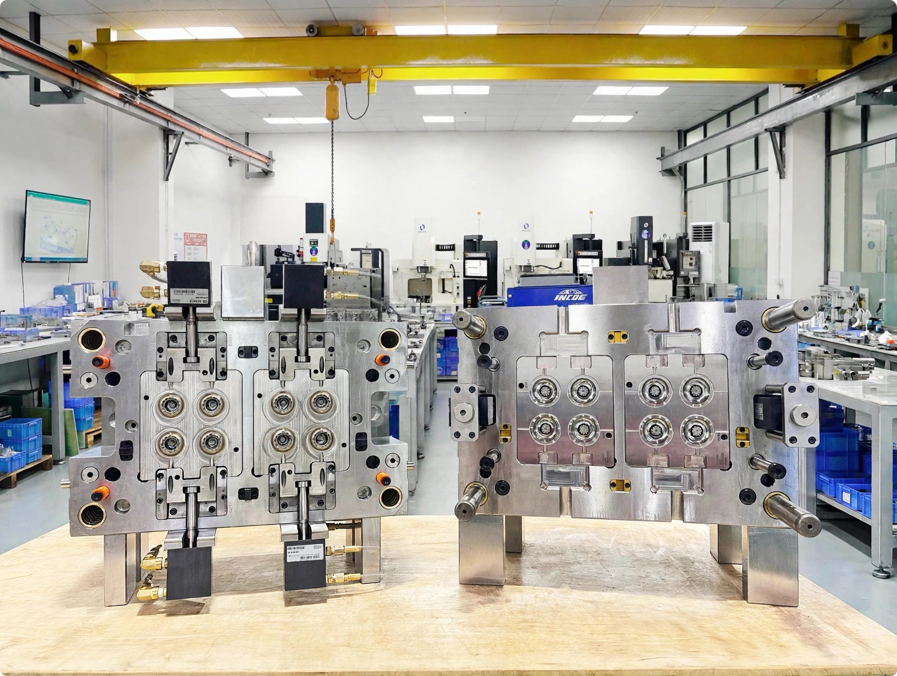
Open multi-cavity injection mold halves on a workbench
Start with what you have

Discuss Your Injection Mold

Share your 3D model and 2D drawing, then add the resin, expected demand, receiving machine, critical features and validation needs you already know.

Project review for custom injection tooling

Have 3D models or 2D drawings? Email your files to peter@wokemolds.com.

Please review our Privacy Policy before sending project details.