Custom mold engineering for gas-assisted parts

Gas-Assisted Injection Molds

Custom mold engineering and manufacture for hollow grips, structural arms and parts with demanding thick-section appearance. WOKE Molds connects the part design, gas route and tool build with the requirements of your receiving production cell.

Share a 3D model or drawing to start.

Cutaway concept of a molded handle with a hollow internal channel
Illustrative hollow-section concept.
Custom mold engineering and manufacture15+ years of team industry experienceExport tooling, built in-house

What changes when gas becomes part of the molding process?

In conventional injection molding, the screw fills the cavity and packing pressure reaches the part through the material gate until the gate freezes. In internal gas-assisted molding, pressurized nitrogen enters the molten polymer through a defined nozzle or mold injector. It advances through or pressurizes a selected thick section while a solidifying polymer skin remains against the cavity surface.

That sequence can create a hollow core or keep pressure acting inside a thick zone after conventional gate-fed packing has weakened. The result may be a lighter section or a cleaner visible face, but the gas path, residual polymer wall and entry witness become engineered product features—not hidden process details.

For purchasing, the deliverable is therefore more than cavity steel. The tool must embody an approved melt route, gas entrance, containment or overflow strategy, cooling and service access. It must also match the controller, nitrogen supply, press signals and safe depressurization logic of the nominated trial and production cells.

Explore how gas-assisted tooling can reduce concentrated material, support surface quality or simplify an assembly—and compare it with conventional tooling before choosing the route.

Applications for gas-assisted injection molds

Grips, structural arms, reinforced housings and visible covers ask different things of the mold. Explore these application concepts by their function, then compare the geometry and approval requirements.

Grips and handles application concept
Application concept

Grips and handles

Part pattern. Long curved or straight grip with a thick hand-contact section, end attachments and local screw bosses.

Function. The outside envelope provides grip comfort, reach and bending depth while the attachment zones carry assembly load.

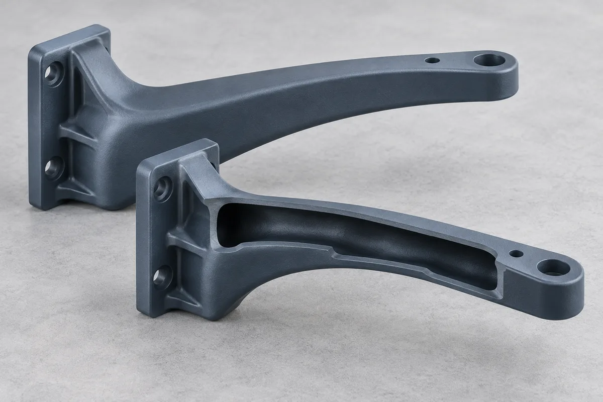
Why gas might help. An internal route can remove mass from the continuous thick core without shrinking the external grip profile. Internal gas pressure may also support the skin along a surface where sink would be visible.

Trade-offs and approval checks

The channel must terminate before weak end walls or loaded bosses. Gas entry, weld lines and gloss changes cannot intrude on the hand-contact or presentation face, and residual wall must support torque and bending requirements.

Approve: Channel route and end, solid boss zones, permissible entry witness, mapped sections at transitions, cosmetic sample, assembly torque and product-level load test where specified.

Structural arms and borders application concept
Application concept

Structural arms and borders

Part pattern. Deep rails, appliance or furniture borders, frame members and structural arms with long load paths or large wall-thickness differences.

Function. Section depth provides bending stiffness, alignment or a rigid perimeter around another component.

Why gas might help. A hollowed thick route can retain useful section depth while reducing a solid mass concentration. Where gate-fed packing struggles to reach the far end, internal gas may extend packing influence along the route.

Trade-offs and approval checks

Corners, forks and abrupt transitions may split or divert gas. A hollow section does not automatically preserve strength; skin position, fiber orientation where relevant, attachment details and load direction all matter.

Approve: Intended main path and branch behavior, solid terminal features, dimensional datum stability, section map at bends and junctions, and the actual stiffness or load acceptance required by the drawing.

Thick ribbed housings application concept
Application concept

Thick ribbed housings

Part pattern. Housings with locally heavy ribs, bosses, perimeter bands or intersections needed for fastening, sealing or stiffness.

Function. The structure supports covers, electronics, motors, fasteners or mating surfaces while the exterior may need controlled flatness and appearance.

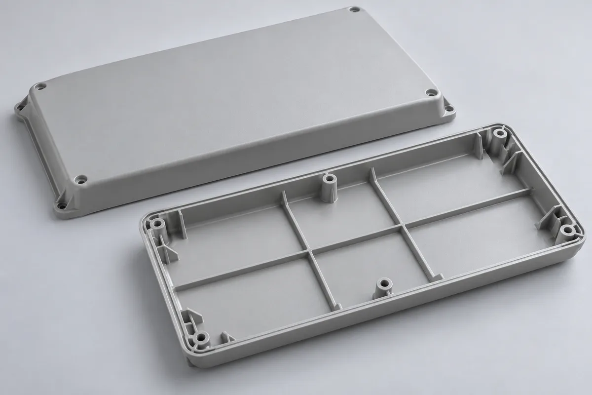
Why gas might help. A deliberately connected heavy route can help pack a sink-prone zone or displace a molten core from a local band. It may allow several heavy features to work as one controlled path instead of isolated masses.

Trade-offs and approval checks

Gas can finger into adjacent thin walls, bypass a branch or approach a seal/fastener feature that must remain solid. Added ribs alone do not create a valid gas route, and asymmetric cooling can still move the housing.

Approve: Gas exclusion zones around seals and threads, thick-to-thin transitions, vent or overflow destination, flatness and fit datums, sections at intersections, and assembly/leak testing when the product requires it.

Cosmetic covers with internal support application concept
Application concept

Cosmetic covers with internal support

Part pattern. Visible cover or trim with a heavy supporting rail, edge roll or concealed reinforcing section behind the show surface.

Function. The outer face carries color, gloss or texture; the concealed structure maintains shape, attachment or stiffness.

Why gas might help. Internal gas inside the polymer may support shrinkage control behind the show face while hollowing the concealed heavy section. External gas is a different route: it applies pressure between the tool and one part surface to support the opposite face and does not make the same internal channel.

Trade-offs and approval checks

Internal gas can shift gloss, hesitation or weld-line evidence if the path approaches the visible surface. External gas requires its own sealing, distribution, equipment and surface-feasibility review.

Approve: A-side and B-side designation, texture and lighting standard, hidden-versus-visible witness rules, internal channel evidence if used, and a separate feasibility decision if external gas is proposed.

Benefits and trade-offs of gas assistance

Gas assist is worth evaluating when a product benefit can justify a more integrated tool and cell. The expected gain should be written into the review and paired with the condition that makes it achievable.

Reduce material concentrated in a thick core

Displacing molten polymer from a deliberately thick route can lower part mass without simply shrinking the outside section.

conditions

The channel must be continuous and contained, and the remaining skin must satisfy strength, fastening and durability needs.

How to evaluate it

Compare finished part mass and functional evidence against a conventional solid or ribbed design; do not approve by hollow percentage alone.

Improve the appearance of heavy sections

Pressure applied inside a still-molten core can compensate shrinkage in zones that a frozen material gate can no longer pack effectively, helping reduce sink or read-through on the opposite face.

conditions

Gate and gas timing, cooling, resin behavior and distance from the visible surface must work together. Gas-entry witnesses, hesitation, gloss shift and weld-line movement remain possible.

How to evaluate it

Approve appearance under agreed lighting and texture conditions together with dimensions and channel evidence.

Keep a deep section for stiffness with less solid mass

A hollow closed or semi-closed section can retain useful geometric depth. This can offer a better stiffness-to-mass direction than filling the entire envelope with polymer.

conditions

Residual-wall distribution, channel position, load direction, material and local attachments determine actual performance.

How to evaluate it

Confirm bending, torque, impact or assembly performance against the agreed product requirements.

Consolidate an assembly

A one-piece molded handle, rail or reinforced cover may replace shells, inserts or joining steps when gas assist makes the thick integrated geometry practical.

conditions

The integrated part must still meet serviceability, cosmetic, tooling and validation requirements. A two-shell assembly may remain the better choice when it provides easier molding or repair.

How to evaluate it

Compare tool and cell complexity against avoided components, joining, inspection and inventory—not piece price in isolation.

Change cooling and packing demands where the design supports it

Removing a molten core can reduce the thermal mass of a heavy section, while internal pressure changes how that zone is packed. Either effect may improve process behavior in a suitable design.

conditions

The tool still needs balanced cooling, a stable release sequence and physical trials. Gas assist does not guarantee a shorter cycle, lower clamp requirement or automatic warpage correction.

How to evaluate it

Treat cycle and stability as trial outputs on the nominated equipment, not assumptions used to justify the mold.

Compare process routes

Choose where the polymer goes

The selected route determines whether gas advances the melt front, supports packing, or displaces resin into an overflow. Compare the tooling implications before fixing the cavity and gas-entry design.

Short-shot

Gas helps complete cavity fill

Conceptual resin and gas distribution for short routeBefore gas With gas Polymer Gas space
Conceptual distribution; geometry and timing are project-specific.
What happens
A controlled resin charge partly fills the cavity; gas advances the melt front through the intended section and supports packing.
When it fits
A continuous route where gas can complete fill without escaping into thin branches or leaving an unacceptable transition.
Tool and production consequence
Shot size, gas start, entry, channel end and venting act as one fill system. Stability depends strongly on the nominated resin and cell.
Approval focus
Fill progression, complete part formation, containment, residual wall, surface transition, dimensions and function.
Full-shot gas packing (without overflow)

Cooling-stage packing after the cavity is filled

Conceptual resin and gas distribution for full routeBefore gas With gas Polymer Gas space
Conceptual distribution; geometry and timing are project-specific.
What happens
Resin completely fills and packs the cavity first. Nitrogen then adds packing influence as the thick core cools and shrinks.
When it fits
A selected heavy zone where additional cooling-stage packing can support surface or dimensional requirements.
Tool and production consequence
Coordinate gate freeze, core temperature, entry and controlled gas release. This route is not a substitute for a separately designed destination when substantial molten-core displacement is required.
Approval focus
Surface response, shrinkage, local gas space, residual wall, dimensions and repeatability.
Overflow

Displaced resin has a receiving cavity

Conceptual resin and gas distribution for overflow routeBefore gas With gas Overflow Polymer Gas space
Conceptual distribution; geometry and timing are project-specific.
What happens
The cavity is filled and gas pushes a molten core toward a dedicated side cavity or overflow.
When it fits
A longer or more directed penetration path where a controlled resin destination improves route control.
Tool and production consequence
Overflow cavity, connection or valve, cooling, ejection, removal, scrap and trim become production equipment and recurring work.
Approval focus
Penetration route, valve or connection behavior, overflow removal, trim witness, scrap handling and stable part results.

Gas-channel and mold design considerations

Gas follows the lower-resistance path available inside a changing melt. The intended channel is therefore created by geometry, material state and timing together—not by drawing a line through the thickest region.

For the process sequence and its relationship to the tooling, see our gas-assist injection molding overview.

Maintain channel continuity

A steady heavy section gives the gas a more legible route. Sudden reductions can stop penetration; sudden enlargements can consume gas or change the remaining wall. The channel end needs enough polymer reserve to contain gas without forming a weak terminal wall.

design output

Released section concept showing the start, transitions, end condition, solid reserves and inspection locations.

Resolve thick-to-thin branching

At a fork, gas does not divide according to design intent; it favors the branch with the easier pressure and thermal path. A thin, hotter or poorly protected branch may attract fingering, while a colder or more resistant intended branch can hesitate.

design output

Branch-by-branch prediction, protected thin zones, gating or geometry changes, and trial checks at each critical junction.

Choose nozzle entry or an in-mold injector deliberately

Machine-nozzle entry can reduce mold-mounted hardware, but it links gas behavior to the sprue, material gate, shutoff, venting and press/nozzle sequence. An injector or pin in the mold places gas closer to the target route, but consumes tool space and requires drilling, sealing, cleaning access and a replacement plan.

design output

Approved entry location and witness, supplier hardware details, press/nozzle interface, release route, access and spare strategy.

Use vents, overflow and cooling to control different problems

Vents allow displaced cavity air to leave; an overflow gives molten resin a deliberate destination; cooling establishes the skin that contains gas and governs shrinkage. None substitutes for the others. Their locations must support the melt sequence without placing a witness or thermal imbalance in a critical area.

design output

Venting, overflow and cooling layouts tied to fill direction, cosmetic zones, ejection, maintenance and production handling.

Judge the hidden channel and the seen finish together

A smooth exterior can hide an off-center or thin residual wall, while an acceptable channel can still leave a gloss shift or entry mark. The trial must connect internal evidence with appearance, dimensions, assembly and functional load.

design output

One acceptance map linking sections or agreed imaging locations to visible zones, datums, bosses and functional tests.

Gas-assisted design review examples

These scenarios demonstrate the questions, choices and approvals used in a gas-assist review. They are engineering examples, not customer projects, trial records or claimed results.

Scenario: long appliance handle with two loaded end bosses

Project brief

The part has a deep grip section, a high-gloss show face and screw bosses at both ends. The destination plant already has a controller, but its available circuit and nozzle arrangement must be confirmed.

Design choices

A solid handle concentrates material and may show shrinkage; a two-shell alternative reduces thick mass but adds joining and a seam. An internal gas route is valuable only if the one-piece envelope and finish justify the added cell control.

The preferred gas path follows the grip but stops before each boss transition so the fastener load remains in solid polymer. The entry is moved to a concealed serviceable area rather than the hand-contact face.

Short-shot and full-shot concepts are compared against the exact resin and gate direction. If neither gives a stable terminal condition without threatening the bosses, the decision returns to ribbed or assembled construction.

Approval checks

Released route and entry; solid boss reserves; controller and fitting interface; section cuts through the center and both boss transitions; appearance under agreed lighting; critical dimensions; screw torque and handle load criteria supplied by the customer.

Scenario: textured equipment cover with a heavy perimeter rail and side branch

Project brief

The cover needs a stable mating flange and a clean textured A-side. A concealed perimeter rail adds stiffness, but one branch approaches a thin wall and a sealing boss.

Design choices

Internal gas could support the heavy rail and reduce the solid mass behind the show surface, but the branch toward the seal is a likely competing path.

The review first tests whether the branch can be reduced, isolated or kept solid. Gate direction, rail continuity, venting and cooling are adjusted around the intended main route. An overflow is considered only if its extra valve, trim, scrap and operator work produce a clearer route than a contained full-shot concept.

External gas is not treated as a shortcut. Because it presses on a part surface rather than forming the internal rail channel, it would require a separate sealing, equipment and surface-feasibility study.

Approval checks

Main-route and branch decision; solid seal/boss exclusion zone; A-side texture standard; rail and branch sections; flange flatness and mating check; overflow handling if selected; destination-cell release and interlock responsibility.

Material choices for gas-assisted parts

Material families help narrow product requirements, but gas penetration responds to the named grade, viscosity curve, fillers, shrinkage, skin formation, color or additives, moisture condition and recycled-content rule. The final mold concept and trial plan must use the approved grade and allowed substitutions.

ABS

Why select it

A candidate for indoor handles, covers or housings where molded color, paintability, dimensional stability and visible appearance are central.

Trade-offs

Operating heat, chemicals, impact, outdoor exposure and compliance must be checked against the named grade. Flow, impact, heat and color packages can change the cosmetic window and gas behavior.

Tool and trial implication

Lock the commercial grade, color/additives, finish or paint requirement, gas entry and A-side zoning; trial the actual appearance standard rather than treating ABS as one behavior set.

PP

Why select it

Useful where low density, chemical resistance and some flex are valued in housings, furniture or consumer components.

Trade-offs

Shrinkage and dimensional movement can be significant; stiffness and surface behavior depend strongly on grade, filler and section. A flowing grade may also enter unintended branches if the route is not contained.

Tool and trial implication

Review warpage datums, surface read-through, branch protection, cooling balance and actual conditioned sample dimensions using the nominated grade.

PA / nylon

Why select it

Considered for structural components, wear resistance and heat performance, often with glass reinforcement.

Trade-offs

Moisture condition changes processing and final dimensions; fiber content and orientation affect flow, surface and mechanical response. Abrasive grades also change wear considerations.

Tool and trial implication

Specify drying and conditioning, filler content, steel or surface protection where justified, gate and channel direction, dimensional conditioning state and functional load tests.

PC/ABS

Why select it

Often evaluated for rigid housings and visible components needing a balance of impact, appearance and processability.

Trade-offs

Cosmetic sensitivity, weld or hesitation evidence, thermal history and grade-specific flow can constrain entry and route choices.

Tool and trial implication

Define the A-side standard, permissible witnesses, resin supplier/grade/color, drying condition, texture or polish, and cosmetic approval together with internal sections.

POM / acetal

Why select it

A candidate for functional handles, mechanisms, wear interfaces or some fluid/chemical-contact duties where low moisture uptake, stiffness, friction/wear behavior and dimensional stability are important.

Trade-offs

Confirm the actual medium, temperature, wear duty, tolerance and processing limits. Copolymer/homopolymer, flow, impact, reinforcement, low-warpage and tribological grades are not interchangeable.

Tool and trial implication

Review the exact supplier grade and processing guidance, channel and containment concept, thermal history, dimensional checks and any leak, wear or chemical-duty test. A supplier portfolio listing gas/water injection does not establish universal POM suitability.

Other thermoplastics

Why select it

A project may require heat, chemical, impact, regulatory or cost properties outside these representative families.

Trade-offs

Family reputation is not enough to infer gas-assist behavior. Filled systems, flame-retardant packages, recycled content and color changes may materially change flow, skin and surface response.

Tool and trial implication

Use supplier data and, when warranted, material-specific analysis and trial evidence before allowing substitutions or releasing sensitive steel features.

Choose resin, mold steel and finish separately.

Resin

Choose the exact commercial grade for product performance and route validation.

Mold steel

Choose for volume, wear or corrosion, service and repair strategy.

Cavity finish

Choose for the visible surface and release; approve it with the internal route.

The resin is chosen for the finished product. Mold steel and replaceable wear details are chosen for expected volume, abrasive or corrosive content, maintenance and repair strategy. Texture, polish or coating is chosen for the visible surface and release behavior. A glass-filled nylon decision may influence steel wear protection and gate direction; it does not mean the resin and steel can be specified as one material choice. Likewise, a mirror or textured cavity does not prove that the internal gas route is sound.

Mold supply and project responsibilities

WOKE Molds’ core offer is the engineered mold: design, manufacture, fitting, correction and export handover around the approved gas route, all in our own factories. The quotation identifies trial equipment, mold-side hardware and plant interfaces so each work package has a clear owner.

Work package WOKE Molds scope Named specialist or trial partner Customer / receiving plant
Part and route review Compare conventional and gas-assisted concepts; develop the approved mold-side route after kickoff DFM. Provide supplier requirements when a specific injector or controller constrains the concept. Supply controlled CAD/drawings, product requirements, resin and target cell information; approve the selected route.
Mold engineering and build Design and manufacture cavity/core, gate and gas-side provisions, cooling, vents, any approved overflow, access, replaceable inlet or wear detail, ejection, mold base and receiving-press fit. Supply or confirm proprietary injector dimensions and installation requirements where applicable. Approve mold layout, steel, component brand, visible witnesses, mold standard and maintenance expectations.
Gas and auxiliary equipment Define mold-side connection and document required interfaces. Include hardware only where the quotation names it. Supply controller, pressure-generation or booster equipment, nitrogen system, valves, hoses, fittings or technical commissioning as agreed. Confirm installed equipment, utilities, signals, guarding, local compliance and plant ownership.
Trial and correction Coordinate a named suitable trial arrangement, record mold issues, implement agreed mold corrections and update affected documentation. Provide compatible gas equipment and operating support when separately contracted. Provide production resin and acceptance criteria as agreed; participate in sample approval and confirm destination-cell differences.
Production Molded-part production can be quoted in our Shenzhen plant once the process, equipment and responsibility boundary are confirmed. Support specialist process equipment as contracted. Own plant qualification, production approval and ongoing safe operation unless the contract assigns a named item elsewhere.
Export and transfer Prepare the mold, agreed records, spares and shipment under quoted trade terms. Provide equipment manuals or certificates for separately supplied systems. Arrange receiving-cell installation and recommissioning responsibilities; accept the tool against the agreed package.

Manufacturing your gas-assisted mold

The gas route only becomes useful when it is translated into steel that can be built, accessed, corrected and transferred. WOKE Molds designs and builds the mold with our own engineering team in our Dongguan factory.

Release the mold layout

After kickoff DFM, the layout fixes cavity orientation, gate and gas entrance, intended channel and end, vents or overflow, ejection, mold standard, destination press fit and service approach. The customer approves visible witnesses, interfaces and functional exclusion zones before affected steel is released.

Choose steel and replaceable gas-side details

Steel follows volume, resin abrasiveness or corrosion risk, surface requirement and repair strategy. Where the inlet or sealing feature is exposed to wear or cleaning, an accessible replaceable detail can reduce the consequence of service damage; its supplier interface and spare requirement are approved rather than assumed.

Machine cooling, vents and connection features to the same design intent

Gas drilling or inlet provisions, water circuits, venting and any overflow must coexist without weakening steel or blocking maintenance. Fittings and hose direction need clearance in the mold and on the receiving press.

Fit, finish and inspect the tool

Assembly checks shutoffs, movement, inlet access, sealing features and component fit. Texture, polish or other required treatment follows the approved visible-surface specification. General mold manufacturing evidence supports this work, but it is not presented as proof of a completed gas-assist project.

Turn trial observations into controlled corrections

Trial feedback is separated into mold changes, gas-equipment or sequence changes, resin-condition issues and product-acceptance questions. Agreed steel corrections are tracked against the released design; affected drawings and records are updated before approval.

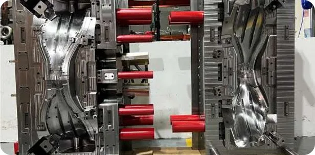
General injection mold tooling manufactured by WOKE Molds
General tooling manufacture shown as company capability—not a gas-assist case result.

Verified company context

  • 15+ years of team industry experience
  • 1,800 m² factory in Chang'an, Dongguan
  • Engineering, tooling, trials and production support from our own factories in Dongguan and Shenzhen
  • General export molds are trialed and inspected before rust protection, packing and shipment

Gas-assisted molding is one of our core technologies, together with two-shot and heat & cool molds, external gas, in-tool venting and CO₂ temperature control.

Gas-assisted mold trials and validation

Analysis can compare routes and expose risk, but acceptance depends on the molded part. The validation plan ties each expected benefit and known failure mode to an observable check rather than treating a good-looking surface as complete evidence.

Expected value or observed risk Engineering control Physical validation Approval decision
Lower mass in the thick route Define the intended channel and solid reserves around attachments. Part-weight record plus mapped sections or an agreed suitable imaging method. Accept only when residual wall and functional tests also meet the drawing.
Reduced sink on a visible face Coordinate gate, gas route, local cooling, resin and permissible witness zones. Cosmetic review under agreed lighting/texture conditions, dimensions and channel evidence from the same configuration. Approve surface and internal condition together.
Fingering into a thin branch Change resistance, geometry, thermal balance or exclusion design at the branch. Sections at the branch and repeat samples, plus dimensional or leak checks where that wall is functional. No gas intrusion into a protected wall beyond the agreed acceptance.
Breakthrough or loss of containment Protect the route end; resolve vent/overflow relation, entry and gas release with the nominated system. Section evidence at the end and repeated molding under the agreed cell condition. Stable containment and safe depressurization before mold opening.
Uneven residual wall or weak attachment Place the channel relative to load path, bosses and cooling; preserve solid reserves. Section map and specified assembly torque, bending, impact, leak or other product test as applicable. Meet product function, not a generic hollow ratio.
Warpage or unstable transfer Balance cooling and packing influence; control resin condition; document destination-cell interfaces. Dimensional report, sample comparison and scoped run on nominated or destination-equivalent equipment. Accept tool and record any remaining recommissioning responsibility.

Sample quantity, section locations, report format and functional limits belong in the project acceptance plan. Trial scope and process development are agreed for the selected part and production cell.

Tooling investment and production cost

A gas-assisted tool may cost more to engineer and integrate than a conventional mold, while a suitable part may use less resin, avoid an assembly or improve the manufacturability of a heavy section. The quotation separates one-time investment from recurring production cost so sourcing can compare the whole route.

Alternative Potential advantage Added burden or limit Best comparison question
Conventional solid mold Simpler cell and transfer; no gas equipment or internal-channel validation. More resin and thermal mass in a heavy route; sink, warpage or machine/cooling demand may still require design work. Can geometry, gating, packing and cooling meet appearance, mass and function without gas?
Conventionally cored and ribbed mold Avoids gas integration and can create a reduced section when ordinary core steel has access. May require deeper core steel, slides/lifters, rib and boss redesign, more demanding ejection or cooling, and can show rib read-through. Can accessible core steel create the required shape with a lower total tooling and production burden?
Two-shell or multi-piece assembly Each shell can be thin and conventionally molded; hidden internal geometry is accessible. Additional tools or cavities, joining, seam appearance, inspection, inventory and possible leak or strength concerns. Does avoided assembly complexity justify the gas-assisted one-piece route?
Short-shot internal gas Can complete a hollow route with less initial resin in a suitable continuous section. Greater sensitivity to charge, melt progression and containment; requires cell control and channel validation. Is the fill route stable enough for transfer with the exact resin and destination cell?
Full-shot gas packing Adds packing influence during cooling after the cavity is filled and packed with resin. Requires coordinated gate/core thermal state, gas entry and release. Substantial core removal requires a separately designed resin destination. Does additional gas packing improve the target surface or dimensions on the nominated cell?
Overflow route Creates a deliberate destination that can extend or steer penetration. Adds tool features, control, scrap, trim, handling and maintenance. Is the improved route control worth recurring overflow work and material?
External gas evaluation May support a visible face from the opposite surface without creating the same internal channel. Separate sealing, gas distribution, equipment and surface-feasibility requirements; confirm the supply scope before selection. Is surface support the goal, or is an internal hollow structural section actually required?

Separate project investment from production costs

ONE-TIME / PROJECT

One-time mold investment

Cavity and core complexity, gas drilling or inlet detail, replaceable hardware, overflow or valve features, cooling, surface finish, mold standard, spares and receiving-press fit.

ONE-TIME / PROJECT

Cell integration

Controller or gas equipment, nitrogen source, hoses and fittings, machine signals, interlocks, guarding, installation and specialist commissioning where required. These items are priced by the named responsible party.

ONE-TIME / PROJECT

Validation and transfer

Trial-platform access, resin, sectioning or imaging, dimensional/cosmetic/functional reports, correction work, destination-equivalent verification and receiving-plant recommissioning.

RECURRING / PRODUCT

Recurring production cost

Net resin per accepted part, nitrogen and utilities, overflow scrap and trimming, cycle behavior, rejects, operator work, maintenance and replacement gas-side components.

RECURRING / PRODUCT

Product and assembly effect

Part mass, avoided shells or inserts, joining and inspection, inventory, packaging and field-performance requirements. These can outweigh a narrow tool-price comparison in either direction.

From inquiry to mold delivery

The schedule is developed around part complexity, the mold specification, equipment readiness and the approvals below. Agreeing each decision at the right stage helps avoid late steel changes and trial delays.

Initial files and quotation assumptions

WOKE Molds’ work

Review the 3D model, 2D requirements, thick sections, cosmetic faces, loads, annual volume, resin information and available cell data. Compare a conventional alternative with plausible gas routes and state inclusions, exclusions and open assumptions.

Your review

Confirm controlled files, product priorities, destination, quote basis and who will supply missing resin or cell information.

Schedule dependencies

Part complexity, missing drawings, exact resin, target mold standard, proprietary hardware and whether the receiving cell is already selected.

Kickoff, formal DFM and design approval

WOKE Molds’ work

Develop the parting, gate, gas entry and route, cooling, vents/overflow, ejection, steel, finish, service details and interface plan. Identify analysis and physical validation required.

Your review

Approve DFM decisions, visible witnesses, route, layout, steel/components, acceptance plan and responsibility matrix before affected steel or long-lead items are released.

Schedule dependencies

Decision turnaround, design iterations, component confirmation, analysis needs and destination press/controller details.

Build and progress updates

WOKE Molds’ work

Order approved steel/components, machine, fit, finish and inspect the mold. Share weekly photo updates and track technical issues or deviations that need a decision.

Your review

Approve any change that affects part geometry, surface, interface, cost or delivery basis.

Schedule dependencies

Steel and component availability, machining complexity, treatments/texture, replaceable inlet details and approved engineering changes.

Coordinated gas trial and corrective feedback

WOKE Molds’ work

Arrange the named suitable trial setup, verify mold operation and gas route, collect the agreed samples and evidence, classify issues, and implement approved mold corrections.

Your review

Review samples and reports against the acceptance plan; decide whether remaining items belong to mold correction, equipment/sequence development, resin control or product specification.

Schedule dependencies

Trial-machine and gas-equipment availability, production resin, specialist participation, test/report turnaround and the nature of corrections.

Acceptance, export and receiving check

WOKE Molds’ work

Close agreed mold issues, prepare the handover package, protect and pack the tool, and ship under the quoted Incoterm.

Your review

Sign sample/tool acceptance or the agreed open-item list; prepare the receiving press, gas equipment, utilities and local safety approval; complete installation and recommissioning checks.

Schedule dependencies

Final evidence approval, spare/document completion, freight mode, customs, installation readiness and differences between trial and destination cells.

Before shipment, compare the nominated trial and receiving cells and agree which checks must be repeated at destination. The handover checklist below records those responsibilities.

Export handover and production transfer

Plan both pre-shipment tool acceptance and receiving-cell commissioning. The quotation defines the evidence, responsibilities and sign-off at each stage.

Handover item Supplier responsibility Customer acceptance / receiving check
Released mold and interface information Provide the agreed mold drawings, gas inlet/interface detail, connection requirements and change status. Verify document revision, press fit, nozzle or injector arrangement, connection orientation and plant compatibility.
Mold and gas-side service items Provide the quoted replaceable inlet/injector details, seals, wear/spare list, fitting specification and maintenance access information. Inventory supplied items; confirm local replacement source, tooling and safe maintenance procedure with the equipment supplier.
Approved product evidence Package agreed samples, dimensional/cosmetic records, channel sections or imaging results and applicable assembly/functional results. Compare shipment records with the signed acceptance plan and retain masters under controlled conditions.
Process and safety boundary Record nominated trial equipment, known setup boundary, intended gas-release path and responsibility matrix; include specialist documentation received under the contract. Complete plant risk assessment, interlock and depressurization verification, guarding, utilities and local operating approval before production.
Mold preservation and shipment Apply agreed rust protection, secure moving parts, pack and mark the tool, and provide shipping documents for the quoted term. Inspect packaging on arrival, record transport damage, clean/preserve as required and verify all loose components and documents.
Destination recommissioning Support to the level quoted and identify differences from the trial cell that need resolution. Install on the nominated press, reconnect gas equipment, verify safe release, reproduce acceptance checks and approve production under plant procedures.

EXW, FOB or DDP delivery terms are confirmed in the project quotation, together with the agreed documentation and handover scope.

Gas-Assisted Injection Mold FAQs

Can an existing conventional mold be converted for gas assist?

Sometimes, but available steel is only one condition. The review must find a workable entry, continuous route, safe release path, sealing and service access without compromising cooling, ejection or visible surfaces. It must also confirm the destination controller, press and gas supply. A new insert or new mold is usually the clearer decision when the existing tool cannot contain the path or provide maintainable hardware.

Is gas-assisted injection molding the same as blow molding?

No. Gas-assisted injection molding begins with resin injected into a closed injection mold, then introduces nitrogen into a selected molten section to advance or pack it. Blow molding expands a heated preform or parison to form a hollow body. The part architectures, tools and production cells are different.

Does a gas-assisted part always have a hollow channel?

Internal gas may form a hollow path, but the amount and continuity depend on the selected route. Short-shot and overflow concepts deliberately move the melt, while full-shot gas packing adds pressure as a filled and packed thick section cools and shrinks. Define the product goal and inspection locations rather than assuming a uniform hollow percentage.

Can gas assist guarantee no sink marks?

No. Internal pressure can help compensate shrinkage in a heavy section, but gate position, cooling, resin, surface distance and timing still control the visible result. It can also introduce gloss changes, hesitation or an entry witness. The surface is approved with the internal channel and dimensions from the same trial condition.

What information is needed about the gas controller and nitrogen system?

Provide controller make/model, available circuits, pressure-generation and nitrogen arrangement, machine communication, hoses/fittings, injector or nozzle hardware, alarms and current safety/interlock documentation. The selected equipment supplier and receiving plant approve the actual operating and safety requirements; the mold proposal defines the mold-side interface.

Who develops the production recipe?

Responsibility is assigned in the quotation and interface plan. Mold trials establish evidence on named equipment, but production settings must be commissioned and approved for the destination press, controller, resin condition and plant procedures. A transferred mold does not make settings from a different cell universally valid.

Can the exact resin or color be changed after tool approval?

A change may alter flow, skin formation, shrinkage, surface and gas penetration even within the same resin family. Proposed substitutions should be checked against supplier data and the approved route; critical changes may require new samples, channel evidence and dimensional or cosmetic revalidation.

How are internal channels inspected without cutting every part?

Development commonly uses mapped section cuts because they directly reveal wall distribution at selected locations. A suitable non-destructive method can be agreed when geometry, material, access and cost support it. Production control may then combine approved process limits, part weight, dimensions and sampled internal checks; the plan is defined for the actual risk rather than promised as a universal method.

Can WOKE Molds produce the molded parts as well as the mold?

Yes. Production can be quoted in our Shenzhen plant after a suitable cell, gas equipment, resin, validation and responsibility boundary are confirmed. It is quoted separately from the tooling, and the proposal names who supplies and operates the gas system.

What is the difference between internal and external gas assistance?

Internal gas enters the molten polymer and may form or pressurize an internal path. External gas acts between the tool and one part surface to support the opposite face. It requires separate sealing, equipment and surface-feasibility evaluation; confirm that route and its supply scope in the proposal.

Why might a conventional mold still be the better choice?

A conventional design may win when the part can meet mass, sink and stiffness needs through wall reduction, ribs, coring, gating or cooling; when the gas path branches unpredictably; or when the receiving plant cannot support the required gas equipment and controls. The purpose of the review is to select the lower-risk total solution, not to force gas assist into every thick part.

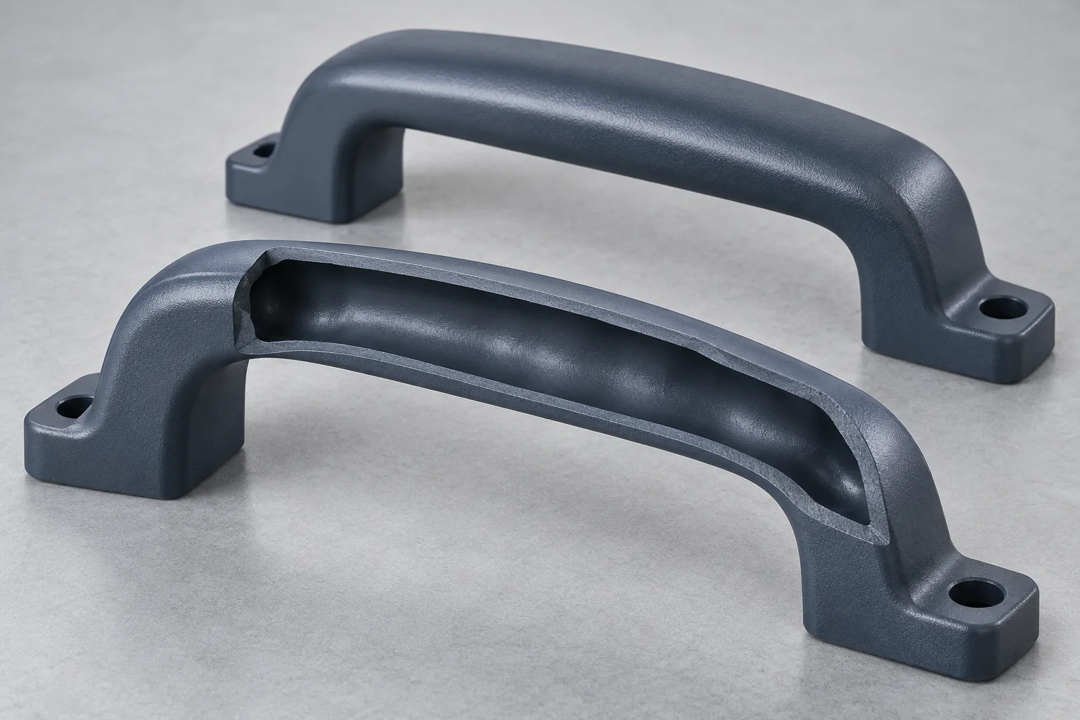
Illustrative cutaway of a molded handle with an internal gas channel
Start with what you have

Discuss Your Gas-Assisted Mold

Share the CAD and drawing. Mark thick sections, cosmetic faces, functional loads and the intended receiving cell; add the exact resin grade when known.

Illustrative hollow-section concept

Have 3D models or 2D drawings? Email your files to peter@wokemolds.com.

Please review our Privacy Policy before sending project details.