Mold design services · DFM review

Engineering & DFM

Agree how the part will release, fit and be inspected.

We review your model and drawing to flag manufacturing risks for quotation. After a mold project starts, formal DFM and our mold design services in Siemens NX identify the design decisions your team needs to approve before we build the tool. See our guide to injection molding tool design.

For injection molds, molded parts and CNC components.

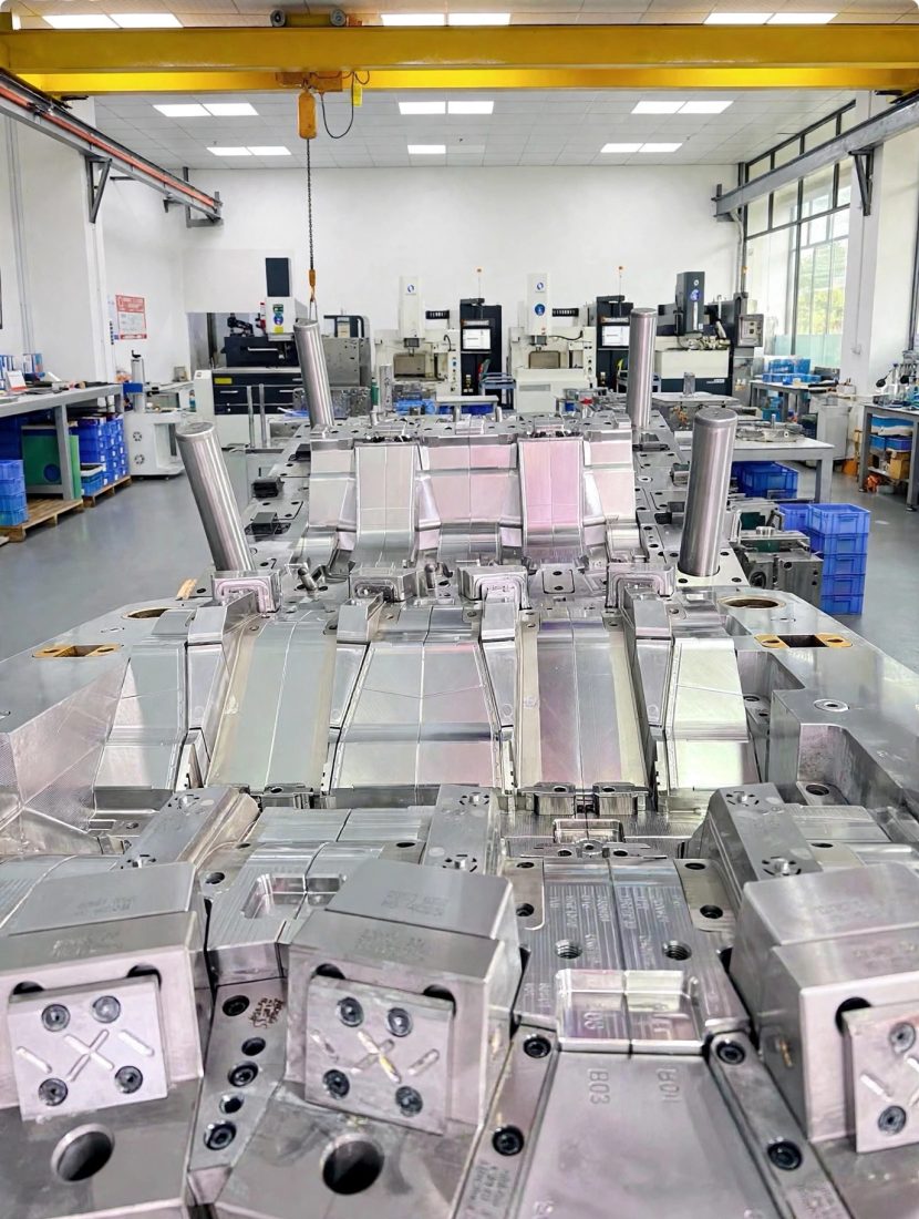
Close-up of a metal injection mold showing multiple cavity features
Close-up of cavity features in an injection mold.
Part functionManufacturing accessAgreed acceptance

Two stages, different decisions

What gets reviewed before and after kickoff?

DFM means design for manufacturability. Its useful output is a decision your team can approve, with the assumptions and verification work still visible.

RFQ and preliminary review

Identify what affects the route and quotation

Send the current 3D model and 2D drawing, material or grade, quantity, target finish and critical features. Mark unresolved details and tell us whether you need a mold, finished parts or both.

Preliminary feedback identifies feasibility questions, missing inputs and proposed scope. It does not replace a released drawing, formal mold design approval or physical validation.

After project kickoff

Resolve the manufacturing design for release

For an agreed mold project, formal mold DFM and 2D/3D mold design review address parting, gating, ejection, cooling and required actions. Your team confirms product changes and the agreed mold design before manufacture proceeds.

Deliverables, approval points and trial records belong in the agreed project scope. CNC projects need their own process and acceptance review.

The review desk

One housing. Three engineering decisions.

Follow an illustrative housing through three review questions. Select a feature to see the proposed change, the decision to approve and the check needed at trial.

Housing section with a solid boss and a cored alternative A thick solid boss below the cosmetic face is compared with a cored boss. Arrows identify local mass and the proposed core opening. SECTION A–ASolid bossCored alternative Cosmetic face Local mass Core openingIllustrative only · No dimensions implied
Section through a housing face and internal boss.

Wall & boss

Can the boss be cored and still carry the load?

Decision
A thick rib or boss under a cosmetic face may create appearance and cooling concerns.
Alternative
Review coring, rib layout or a relocated attachment while preserving assembly strength.
What you approve
Approve the geometry and the acceptable appearance zone.
Verify
Check fastening loads, fill behavior and trial parts for sink, distortion and fit.
Housing hook section with downward core withdrawal and horizontal slider retraction The roof closes the top of both sections. At left a hook projects into the cavity. The main core withdraws downward through the opening to the left of the hook. A separate slider retracts leftward from the open pocket above the hook. The alternative has no hook and allows downward core withdrawal through an unobstructed opening. SECTION B–BHook and side actionOpen feature option Slider retracts Core withdrawsCore withdrawsIllustrative only · Arrows show separate tool movements
Section through a housing edge with a retention feature.

Tool release

How will the retention hook release?

Decision
An undercut can require side action, lifter movement or a product change.
Alternative
Compare added tool movement with an opening or revised retention feature.
What you approve
Confirm retention function, visible witness lines and the selected tooling scope.
Verify
Review movement clearance, draft, ejection and assembly performance at trial.
Seated mating lid with pilots inside housing recesses and datum A on the seating shoulder A lid seats directly on the housing shoulders at datum A. Two pilots project down into open recesses in the housing walls. A horizontal dimension marks the clearance between the right face of the left pilot and the adjacent recess wall. The pilots stop above the recess floors.SECTION C–CMating lid ASeating datum Side clearanceHousingIllustrative only · Fit values require an agreed drawing
Seated lid with pilots in recesses and clearance at the mating interface.

Fit & datum

What locates the lid during inspection?

Decision
A nominal gap alone does not define functional acceptance.
Alternative
Agree datums, mating limits and a measurement or assembly check.
What you approve
Release critical dimensions and the inspection reference condition.
Verify
Check the tolerance stack and physical fit after molding, machining or finishing.

Inputs that change the review

Start with the manufacturing route.

The same model can lead to different questions. Include the operating and acceptance conditions that a drawing alone cannot explain.

Injection mold

Identify the receiving press, cavity target, resin, expected use, mold standard and required interfaces. Confirm who will run trials and accept the tool.

Agree mold DFM, 2D/3D mold design approval and trial evidence within the tooling scope.

Mold manufacturing

Molded parts

Provide resin grade, color, finish zones, quantity and critical-to-quality features. Identify supplied tooling and any molding or assembly constraints.

Agree part acceptance, trial feedback and production requirements separately from tool ownership.

Molding processing

CNC components

Specify stock material, datums, access restrictions, surface finish and fits. State whether dimensions apply before or after coating or treatment.

Review setups and inspection references against the released component drawing.

CNC machining

From questions to release

Keep a decision trail.

Confirm the file revision and scope. Review risks and alternatives. Record buyer approvals. Then manufacture, trial and compare the results with the agreed requirements.

Moldflow may be proposed for complex geometry or on customer request. For example, a gate position may move its vestige away from a visible face but shift a weld line toward a loaded boss or insert. Identify the protected zone and compare flow options using stated material and process assumptions. Validate the selected approach against trial conditions and measured parts.

Before you send the files

Practical questions

Make the unresolved decisions visible early.

Can we start while the drawing is incomplete?

Yes. Mark what is provisional and identify the decisions you need help reviewing. Quotation assumptions and release requirements must be resolved before the affected work proceeds.

Which files should our team send?

Send the latest 3D model and dimensioned 2D drawing where available, with matching revisions. Include material, quantity, finish, critical features, mating information and the intended manufacturing route.

Does every project need Moldflow?

No. Use a defined question to decide whether simulation adds value. Agree the analysis scope, input data and expected output before treating it as a project deliverable.

Who approves product and mold changes?

Your authorized team approves product requirements and proposed geometry changes. For mold projects, agree the mold design approver and the review record before release.

How should we specify a cosmetic surface?

Mark visible zones and reference samples or finish standards. Identify acceptable gate, parting and ejector locations, then agree how appearance will be checked on trial parts.

What happens if trial parts miss a requirement?

Compare the result with the approved revision, material and trial conditions. Review the cause and proposed correction, then agree any design change and the evidence needed for another evaluation.

Bring the open questions

Start a technical conversation.

Tell us what the part must do, which route you are considering and what is still undecided. Email drawings and models with their revision references.

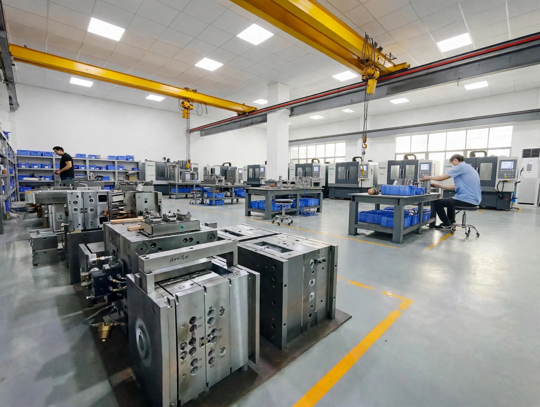
Mold assemblies and technicians at tooling workshop benches
Mold assemblies and technicians at workshop benches.

Review the route, the assumptions and the next approval together.

Have 3D models or 2D drawings? Email your files to peter@wokemolds.com.

Please review our Privacy Policy before sending project details.