
Multi-Cavity Injection Molds
Produce multiple identical parts per cycle with a mold planned for your resin, annual demand and receiving press.
WOKE Molds designs, machines, fits and trials the mold in our own factory in Chang’an, Dongguan, and can run series production in our Shenzhen molding plant. We connect cavity layout, runner selection, cooling and acceptance requirements so your tooling quotation and production plan share a clear technical basis.
- Part and resin-led architecture
- Receiving-machine interfaces reviewed
- Acceptance traceable by cavity
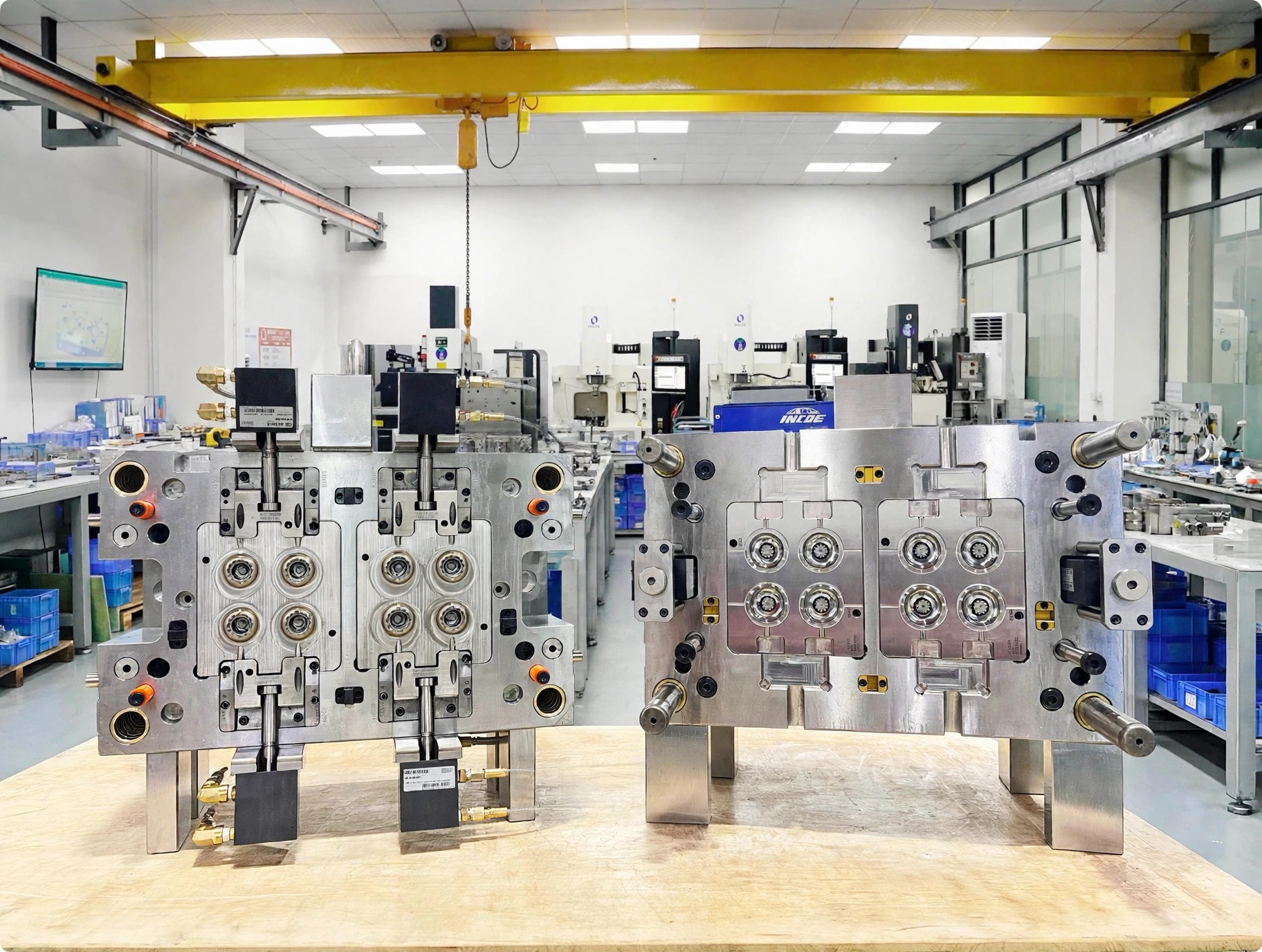
When Multi-Cavity Tooling Fits Your Production
A multi-cavity mold is most useful when the part definition and demand justify the added tooling, press and maintenance complexity. It is not automatically the right answer for an unstable design, uncertain resin, low utilization or a part whose loading and mold actions dominate the cycle.
Multi-cavity is different from family tooling. A multi-cavity mold repeats the same part. A family mold combines different parts, adding another layer of fill, cooling and demand balancing that should be reviewed separately.
- Part maturityGeometry, interfaces and critical characteristics are stable enough to support repeated cavities and a controlled change process.
- Demand basisAnnual demand, program horizon, target output and expected utilization provide a credible basis for comparing investment and operating exposure.
- Process windowThe resin, filling behavior, ejection, appearance and critical dimensions leave a practical window across all cavities.
- Production cellThe intended press, services, handling and operator or automation method can accommodate the mold and its operating needs.
- Maintenance modelThe receiving team can support the selected runner, inserts, wear items and preventive-maintenance approach.
Part Requirements That Shape the Tooling
From small clips to cosmetic housings, geometry, resin, handling and appearance requirements shape the tooling approach.
-
Small clips and fasteners
Repeated, stable geometry can suit higher cavitation when feed paths, ejection and wear points remain serviceable.
-
Connectors and electrical parts
Critical interfaces, thin features or reinforced resin make gate location, venting, insert wear and cavity-specific inspection central to the decision.
-
Caps and closures
Output goals may favor more cavities, while gate design, cooling access, unscrewing or stripping behavior can set the practical limit.
-
Insert-loaded parts and cosmetic housings
Loading method, gate witness, weld lines, texture and cavity-to-cavity appearance may matter more than the nominal number of cavities.
Choose the Right Cavity Count
We compare cavity count against projected area and clamp demand, total shot volume, mold envelope, feed-path pressure loss, cooling access, ejection, actions, maintenance and the expected production plan. Symmetry can help, but a symmetrical drawing does not by itself prove balanced filling.
- Inputs
- 3D and 2D files, exact resin or candidates, annual demand, critical features, finish, intended press and production goals.
- Review
- Evaluate fill-path timing, runner volume, gate access, cooling, mold actions, projected area, shot use and service access together.
- Buyer consequence
- A defendable comparison between output potential, tool investment, machine class, material per accepted part, changeover and downtime exposure.
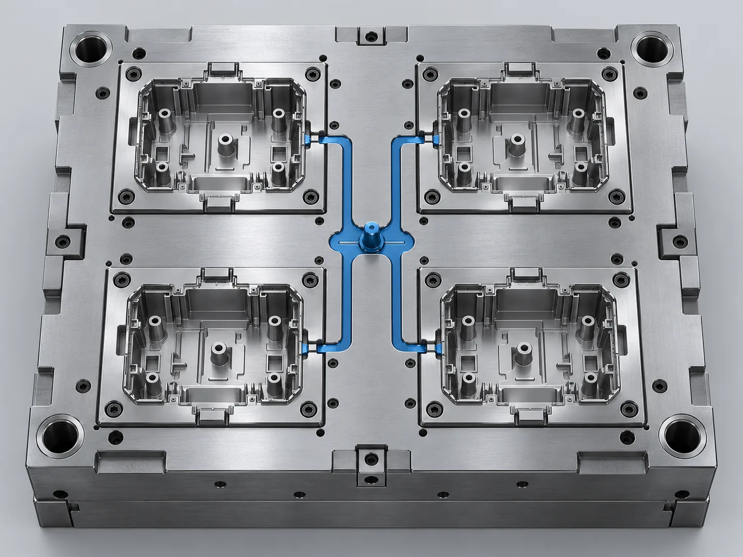
Tooling Investment & Quotation Scope
Compare cavity options using the same resin, tool construction, trial requirements and delivery responsibilities. Clarify component standards, trial-material supply and acceptance records early so differences between quotations are visible before you commit.
| Comparison item | What should be explicit | Why the buyer needs it |
|---|---|---|
| Architecture | Cavity count, mold envelope, actions, inserts, cold or hot runner and controller scope | Shows what is actually included and what the receiving cell must support. |
| Materials | Steel grades, heat treatment, mold base, components, wear or corrosion response | Connects purchase price with service conditions, repairability and maintenance. |
| Validation | Trial material and quantity, inspection characteristics, cavity traceability, reports and acceptance route | Prevents unequal evidence packages from being treated as equivalent. |
| Delivery | Spares, documents, packing, delivery term, installation information and site support if scoped | Exposes handover work and costs that otherwise appear after tool completion. |
| Production basis | Machine class and time, runner material, utilization, changeover, maintenance and downtime exposure | Helps compare the total cost of producing accepted parts. |
Runner, Cooling & Ejection
The exact resin grade changes more than nominal shrinkage. Viscosity, filler and reinforcement, additives, color, drying, thermal sensitivity and processing window influence gates and runners, venting, cooling, surface appearance, steel wear and trial conditions. Published shrinkage data is an input; geometry, wall thickness, flow direction, gate, packing and temperatures affect the realized result.
A balanced feed concept seeks suitable fill timing with controlled pressure loss and runner volume. It is assessed with the actual part and process basis, not promised from geometry alone.
For the layout decision, compare multi-cavity and family molds against the required part mix and production demand.
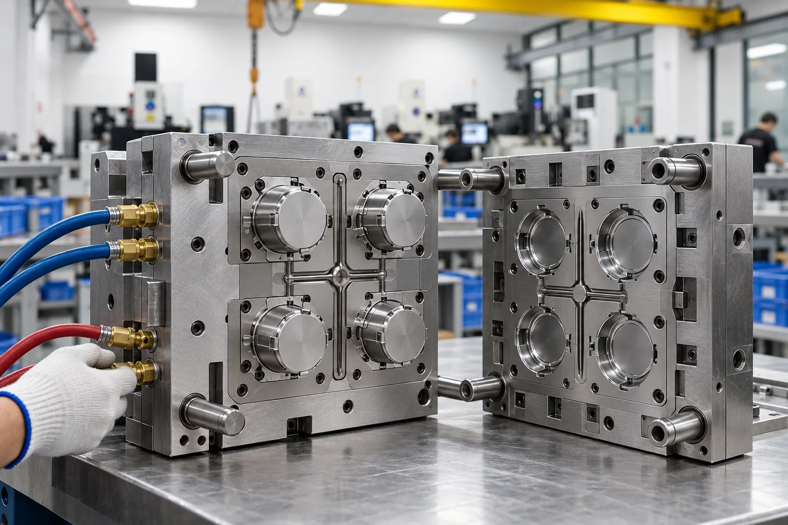
Cold or hot runner
Compare allowable runner material, resin sensitivity, gate and appearance needs, color changes, controller interfaces, maintenance skill, spare access and initial investment. A hot runner can reduce cold-runner material but adds heaters, sensors, seals, tips and service requirements.
Steel and replaceable inserts
Use resin, fillers, finish, corrosion environment, program horizon and critical wear zones to balance wear resistance, corrosion resistance, toughness, polishability and repair. Replaceable gate, core or cavity inserts can improve maintainability where the design and risk justify them.
Cooling, venting and ejection
Cooling access, vent paths and ejection must work across every cavity without creating inaccessible service areas. Side actions, unscrewing, insert loading and cosmetic surfaces can set a more practical cavity limit than available mold space.
Receiving-machine data needed before design release
- Machine make, model and current data sheet
- Tie-bar spacing and usable platen envelope
- Minimum and maximum mold height
- Opening, daylight and clamp capacity
- Injection unit, screw and available shot volume
- Nozzle radius, orifice and locating ring
- Mounting pattern and ejector interface
- Cooling, hydraulic, pneumatic and electrical services
- Hot-runner controller and connector standards
- Handling, lifting and site limits
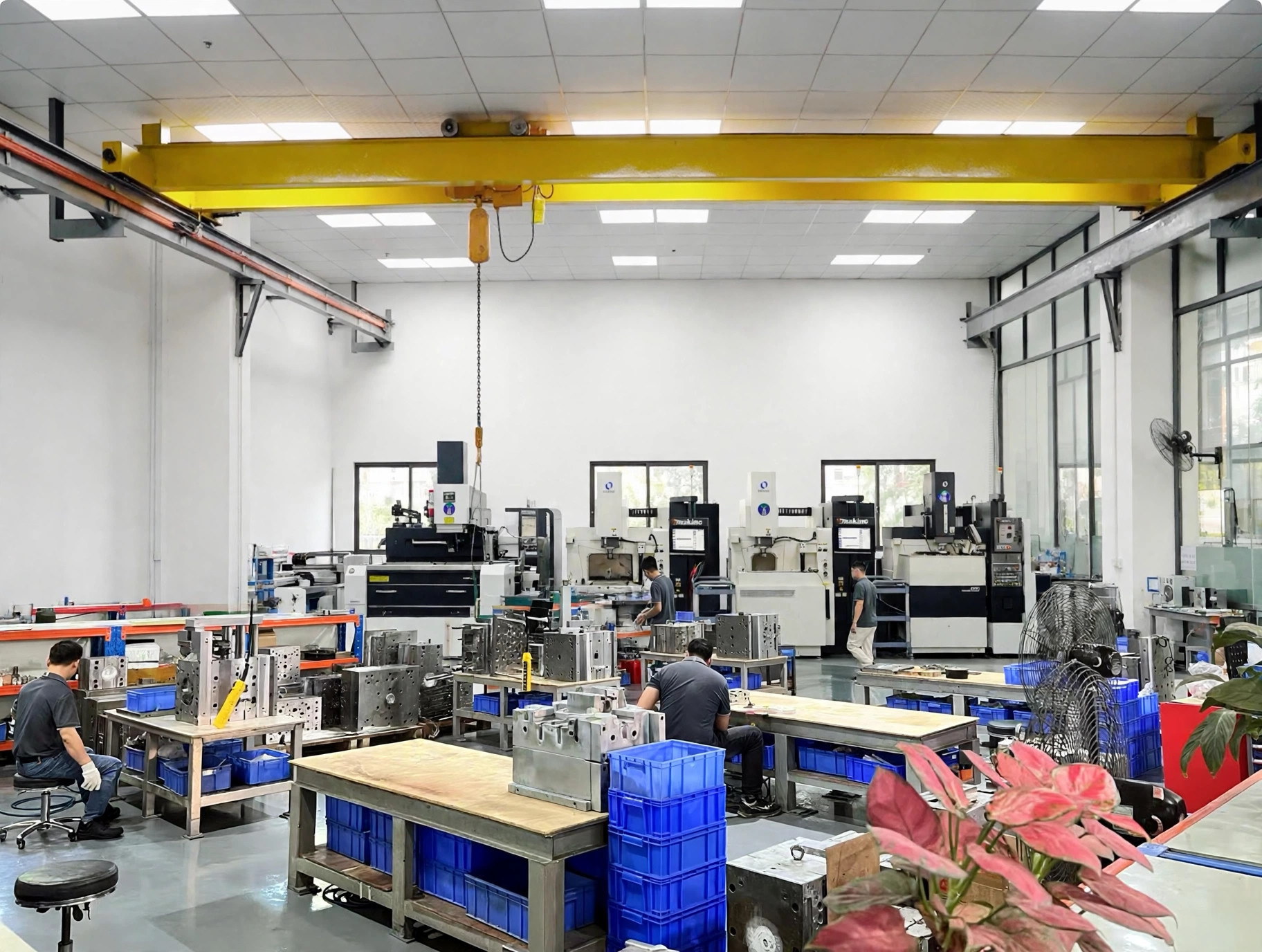
From Mold Design to Cavity-Level Acceptance
After project kickoff, formal DFM turns the part, material and machine requirements into the mold design basis. The engineers who design your mold also follow its build and trials, so changes reach the toolmakers directly.
Cavity-traceable evidence
- Cavity identification where suitable
- Segregated and labeled samples
- Trial date and revision
- Resin grade, lot and conditioning
- Machine and key settings
- Method and critical characteristics
- Results by cavity
- Appearance, fit or function observations
- Open actions and disposition
- Design release
Resolve parting, gates, runners, cooling, venting, ejection, actions, steel, interfaces and service points against the agreed inputs.
- Steel and component preparation
Procure and verify the defined materials and components, then machine cores, cavities, electrodes and supporting mold features.
- Fitting and assembly
Fit moving interfaces, inserts, shutoffs, ejection and feed components while checking access for assembly and future maintenance.
- Trial and review
Run with the agreed resin and documented conditions, segregate samples by cavity, and evaluate the specified dimensions, appearance and functions.
- Correction and acceptance
Record actions and revisions, repeat the agreed checks where needed, and route the evidence for customer disposition before handover.
Define what travels with the mold
Prepare a handover package your molding team can use. Define the documents, operating connections, service items and destination requirements during quotation and design review, while they can still be incorporated into the tool.
Identification also matters after installation. Cavity marks, replaceable components, water circuits, electrical connections and lifting points should be understandable to the people who set, run and maintain the mold. Agreeing that language early reduces ambiguity when a wear issue or cavity-specific result needs to be communicated across sites.
- Released informationAgreed design and document set, mold and component identification.
- Acceptance recordsApproved samples, cavity-specific inspection and trial records within scope.
- Operating interfacesCooling and service map, trial or process sheet as scoped, hot-runner documents where applicable.
- Service preparationAgreed spare and wear items, component references and issue route.
- LogisticsPreservation, packing, lifting and installation information, with EXW, FOB or DDP confirmed for the agreed destination.
Multi-Cavity Mold FAQs
Practical answers for scoping, comparing and accepting a production tool.
How is the right cavity count selected?
Cavity count combines part size and geometry, exact resin, critical features, demand, cycle assumptions, feed system, mold actions, destination machine, maintenance approach and tooling budget. A higher count is valuable only when the complete mold and production basis remains practical. We compare alternatives on the same assumptions rather than selecting from annual quantity alone.
How does the resin grade affect the mold design?
Viscosity, shrinkage, reinforcement, additives, thermal sensitivity, drying needs and processing window can change filling, venting, gate wear, cooling, surface appearance and trial conditions. Send the material designation and supplier data when available. If material is open, identify candidate grades so the quotation and engineering review can state their assumptions clearly.
How is shrinkage handled across multiple cavities?
We review the material data together with geometry, wall thickness, flow direction, gate position and size, mold and melt temperatures, packing and cooling. A catalog value is not a universal mold allowance. The acceptance plan should define which dimensions matter, the conditioning basis and how measurement results will remain linked to each cavity.
What does a balanced runner system mean?
The objective is suitable cavity-filling timing with controlled pressure loss, shear and runner volume. A geometrically symmetrical layout is only a starting point. Runner and gate dimensions, resin behavior, part geometry and process conditions must be assessed together. Project-scoped flow analysis may support that review when complexity and agreed risk justify it.
Should we choose a hot runner or cold runner?
Neither is automatically better. Compare resin sensitivity, runner material, gate and appearance requirements, material or color changes, cycle goals, controller standards, maintenance skill, spares and initial investment. Hot runners can avoid much of the cold-runner material, but introduce thermal-control hardware and service needs. The quotation should make the selected system and interfaces explicit.
What press information is required before release?
Provide the target machine make, model and data sheet if possible. Key checks include clamp capacity, injection unit and shot capability for the resin, tie-bar and platen space, mold-height and opening limits, nozzle and locating details, mounting and ejector patterns, plus cooling, hydraulic, pneumatic, electrical and hot-runner connections.
How should steel and tool-life expectations be specified?
Start with the resin and fillers, demand and program horizon, surface finish, wear areas, corrosion exposure and maintenance conditions. Steel, hardness, heat treatment, coatings and replaceable inserts trade wear and corrosion resistance against toughness, polishability, repair and cost. Record the agreed grades and standards instead of relying on an undefined generic life label.
How is cavity-to-cavity consistency checked?
Agree the critical characteristics, cavity identification method, trial and resin conditions, measurement method, sample quantity and acceptance basis. Results remain linked to the cavity and trial revision, with deviations and actions recorded. Dimensional inspection can be one element; appearance, weight, fit, function and process observations may also belong in the project plan.
What drives multi-cavity mold cost?
Important drivers include cavity count, mold size, part complexity, slides or lifters, runner and gate system, resin-related wear or corrosion, steel and heat treatment, cooling, ejection, finish, components, trial material, validation, spares, documents and delivery. Compare quotations on the same scope; tool price alone does not show production fit or operating exposure.
What should be included when the mold ships?
Define the handover package during quotation and design review. It may include released mold information, component and service identification, accepted samples and inspection records, cooling maps, hot-runner documents, scoped process information, spare or wear items, preservation, packing, lifting and installation notes, and shipping responsibilities. Confirm destination compatibility before design release.

Discuss Your Mold Project
Send the part files and requirements you already have. Resin, annual demand and your receiving press help us frame the review.