
Threaded housings and mounting bosses
Define the screw, tightening condition and service load. Thread size alone does not specify whether torque resistance, axial pullout or repeat assembly is critical.
Metal where it matters. Plastic shaped around it.
Custom thermoplastic components molded around threaded hardware, contacts, pins and support features. WOKE Molds builds the mold in our Dongguan factory and molds the parts in our Shenzhen plant.
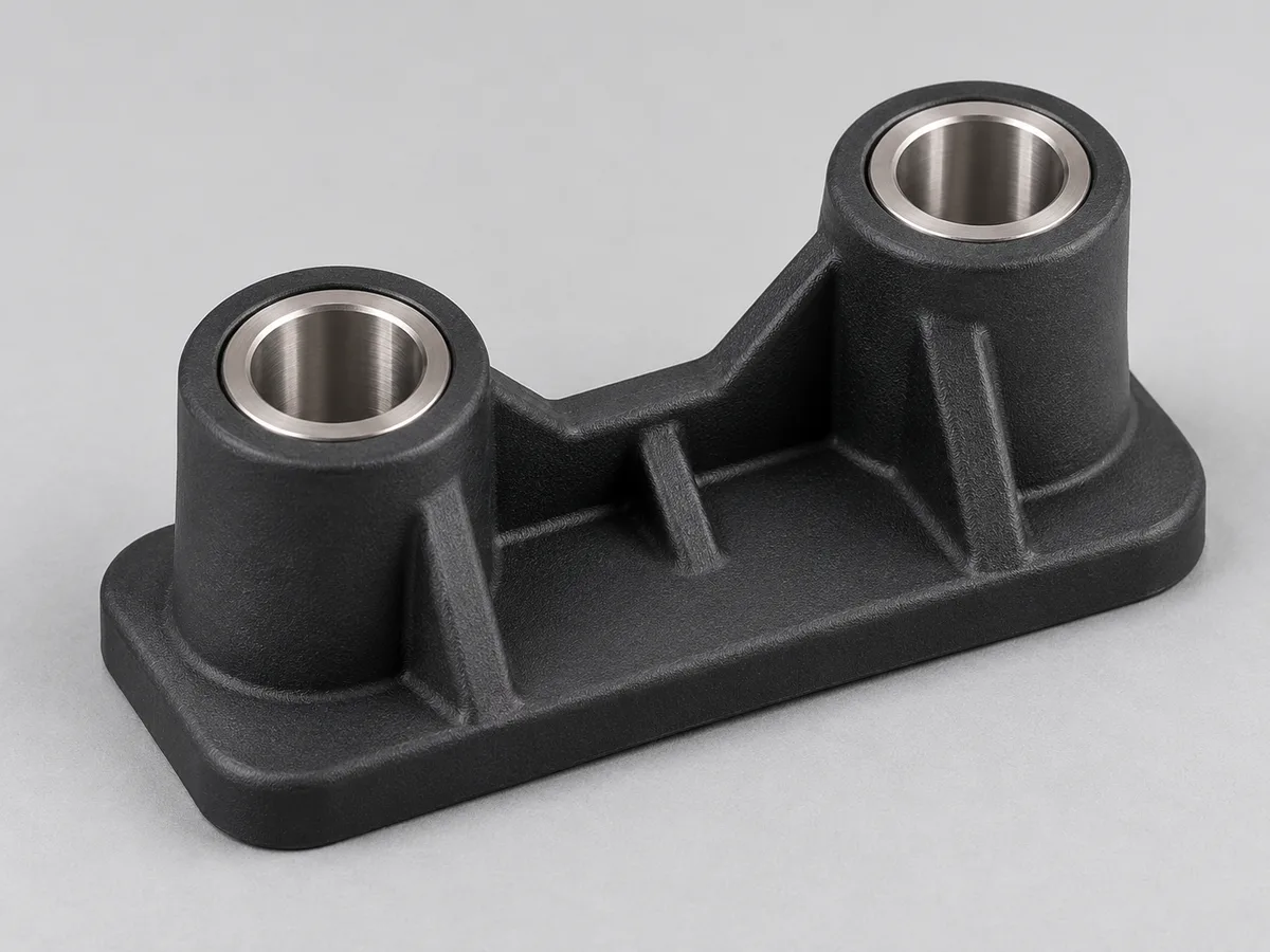
Start with the component's job
The insert is not simply hardware embedded in plastic. It establishes an assembly, electrical or structural interface. Name the function and the critical surfaces so the drawing, mold concept and inspection plan can work from the same requirements.
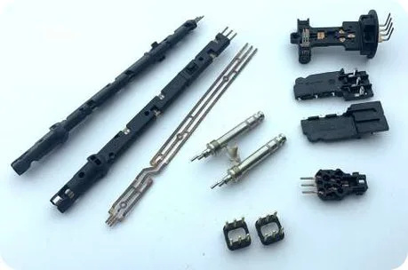
Define the screw, tightening condition and service load. Thread size alone does not specify whether torque resistance, axial pullout or repeat assembly is critical.
Specify terminal pitch, orientation and exposed contact zones. Insulation and electrical behavior depend on the exact grade, geometry and assembly conditions.
Identify the bore, alignment datum and load path. The surrounding plastic needs to locate the feature without obstructing its mating surfaces.
Compare manufacturing approaches
Each route places work, cost and design constraints at a different point in the process. Compare the complete part and its expected order pattern before selecting one.
A preformed insert is positioned in the mold before the plastic is injected. This can integrate the metal feature into the component and control its location within the molded geometry. Insert loading, protection and support become part of the tool and cycle design.
The insert should be integrated at a defined location or a later assembly operation is undesirable.
Loading access, insert stability, protected surfaces, tool shutoffs and the part's retention requirements.
Tooling and locating details, insert handling, cycle profile, order size and inspection scope.
Heat or ultrasonic insertion may suit accessible threaded bosses and a compatible insert style and resin. It shifts the operation after molding, so insertion equipment, settings, access and resulting part condition need to be reviewed for the specific design.
The molded part provides suitable access and a post-mold insert operation fits the assembly plan.
Boss geometry, resin response, insertion controls, cosmetic effects and the required assembly load.
Secondary equipment and labor, fixture needs, inspection and the number of parts handled.
A separate metal component can preserve replaceability or leave room for late design changes. It also retains an assembly step and fastening interface that must be controlled as part of the finished product.
Serviceability, reversible assembly or independent replacement is important.
Fastener access, joint stability, assembly labor and the effect of tolerance stack-up.
Hardware, assembly, inventory and any downstream verification required.
No route is automatically best. Compare geometry, demand, service conditions, required location and the complete manufacturing sequence.
The engineering center of the part
Injection pressure, insert variation, resin shrinkage and assembly forces meet at a small region. The drawing and review should make that interface explicit instead of relying on an assumed fit.
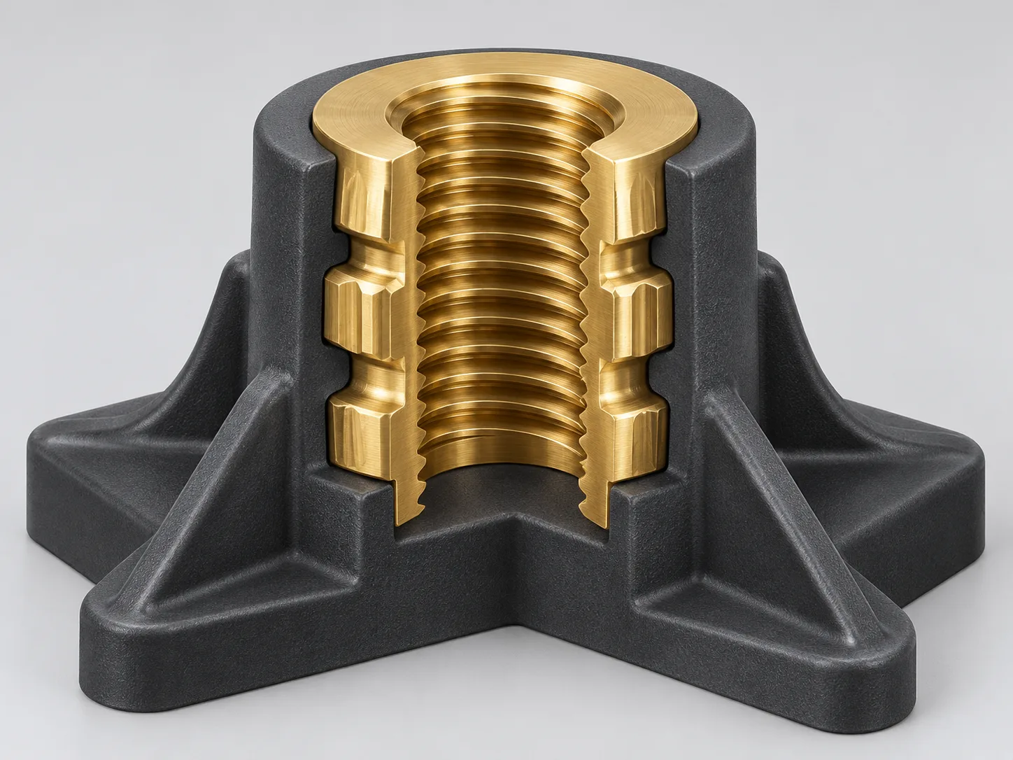
Choose a drawing datum for insert position and orientation. The mold must support the insert against cavity pressure and dimensional variation; the locating method depends on the actual feature and tool.
Torque resistance and axial pullout are different requirements. Knurls, grooves or undercuts may affect them differently, so select geometry around the load direction, resin coverage and assembly use.
Mark resin-free surfaces such as threads, bores and electrical contact faces. Shutoff fit, insert variation, tool wear and the allowed flash condition need project-specific review.
Wall transitions, radii and coverage around a rigid insert influence local stress. Shrinkage and temperature changes can matter; chemical adhesion between metal and plastic should not be assumed.
For review, include the insert drawing, critical datums, resin grade, assembly conditions and any load or environmental requirements. Formal DFM takes place after project kickoff.
Threaded insert design guidance from SPIROL → · How we build the mold and run production →
Pair resin requirements with metal details
Resin selection depends on the part's service environment, load and manufacturing conditions. The exact grade matters more than a polymer family name; the insert's alloy, finish and geometry matter alongside it.
Review moisture exposure, dimensional behavior, heat and electrical function. Reinforcement and fiber orientation can affect local geometry around the insert.
Assess toughness, appearance and the chemical environment together with boss geometry and assembly stress.
For functional or moving features, consider shrinkage and thermal conditions against the insert and mating dimensions.
These may arise in specialized applications. Confirm the exact grade and review process and tooling implications for the specific part.
Supplier data sheets describe a named grade under stated test conditions. A flame rating, for example, applies to a specified grade and test thickness; it does not certify the complete molded assembly.
Control begins with incoming hardware
Whether inserts are customer-supplied or project-sourced, incoming consistency affects location, appearance and repeat production. Set expectations with the insert specification and the order plan.
Agree who provides the inserts before quotation. Record the drawing revision, alloy and finish, critical dimensions, burr and cleanliness expectations, and how lots will be identified. Packaging and orientation matter when exposed contacts or fine features could be damaged.
Manual, assisted or automated loading is selected after reviewing insert geometry, damage risk, order profile and the production cell. The loading method should be verified for the project rather than assumed.
Insert drawing, revision, material and finish.
Critical dimensions, burr limits and clean condition.
Quantity, timing and any allowance for setup or validation parts.
Packaging, lot identification and orientation protection.
The physical molding cycle
The part is shaped around a pre-positioned insert. Each stage connects a physical process condition to a feature that matters on the finished component.
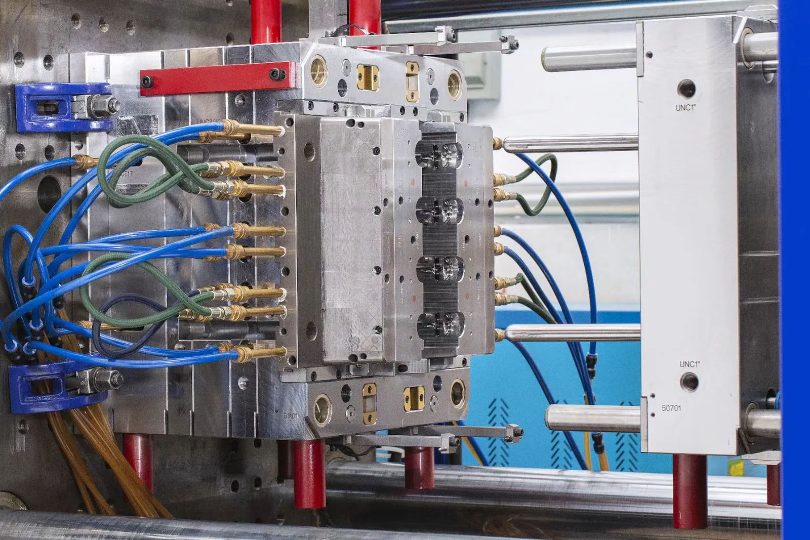
Check the agreed incoming condition, count and orientation. Keep functional surfaces protected during handling.
Seat the insert against the tool's locating features and confirm it is supported before mold closure.
Fill, pack and cool the plastic around the insert. Process conditions and ejection depend on resin, part and tool.
Check the defined appearance, insert position and protected surfaces before the part moves to packing or the next operation.
Connect a symptom to a check
Connect each failure mode to its cause, process review and acceptance check.
Engineering review: Confirm the drawing datum, locating support, insert variation and how plastic flow may act on the insert. Acceptance check: Measure position and orientation against the agreed datums.
Engineering review: Check insert variation, shutoff geometry, tool condition and the resin-free boundary. Acceptance check: Define an inspection method and a functional gauge where appropriate.
Engineering review: Consider wall transitions, sharp edges, shrinkage, assembly load and service temperature. Acceptance check: Agree sectioning, conditioning or a load test when the application calls for it.
Engineering review: Match retention geometry, molded coverage, resin and load direction. Acceptance check: Specify the test fixture, loading direction, conditioning and limits before production.
Engineering review: Review flow path, venting and packing around the geometry. Acceptance check: Define visual, section or application-level criteria for the feature.
Engineering review: Assess handling, seating, orientation and how presence is confirmed. Acceptance check: Agree count, orientation and contact-condition checks for the project.
Define acceptance before the repeat order
Sample approval is a reference point. Ongoing production controls and records should be agreed separately, including what changes require review before a repeat order.
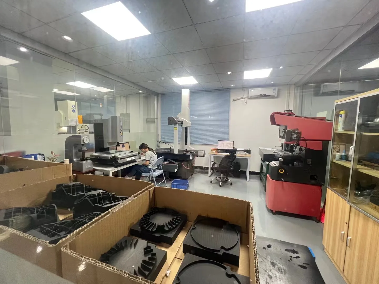
Identify datums and insert position, height, pitch or perpendicularity requirements. Select gauges or CMM measurement when suitable for the feature.
Check thread fit, bore or mating geometry under the specified tightening or assembly condition.
Pullout, torque, thermal exposure, electrical or other tests are scoped only when required, with method, fixture, load and conditioning defined.
Set resin-free zones and acceptable flash, gate marks or flow appearance using clear limits and reference examples where useful.
Agree first-article checks, sampling, in-process or outgoing records and lot traceability to suit the project. A change to resin, insert, plating or tooling can trigger a review before the next run.
Mold and parts from one company
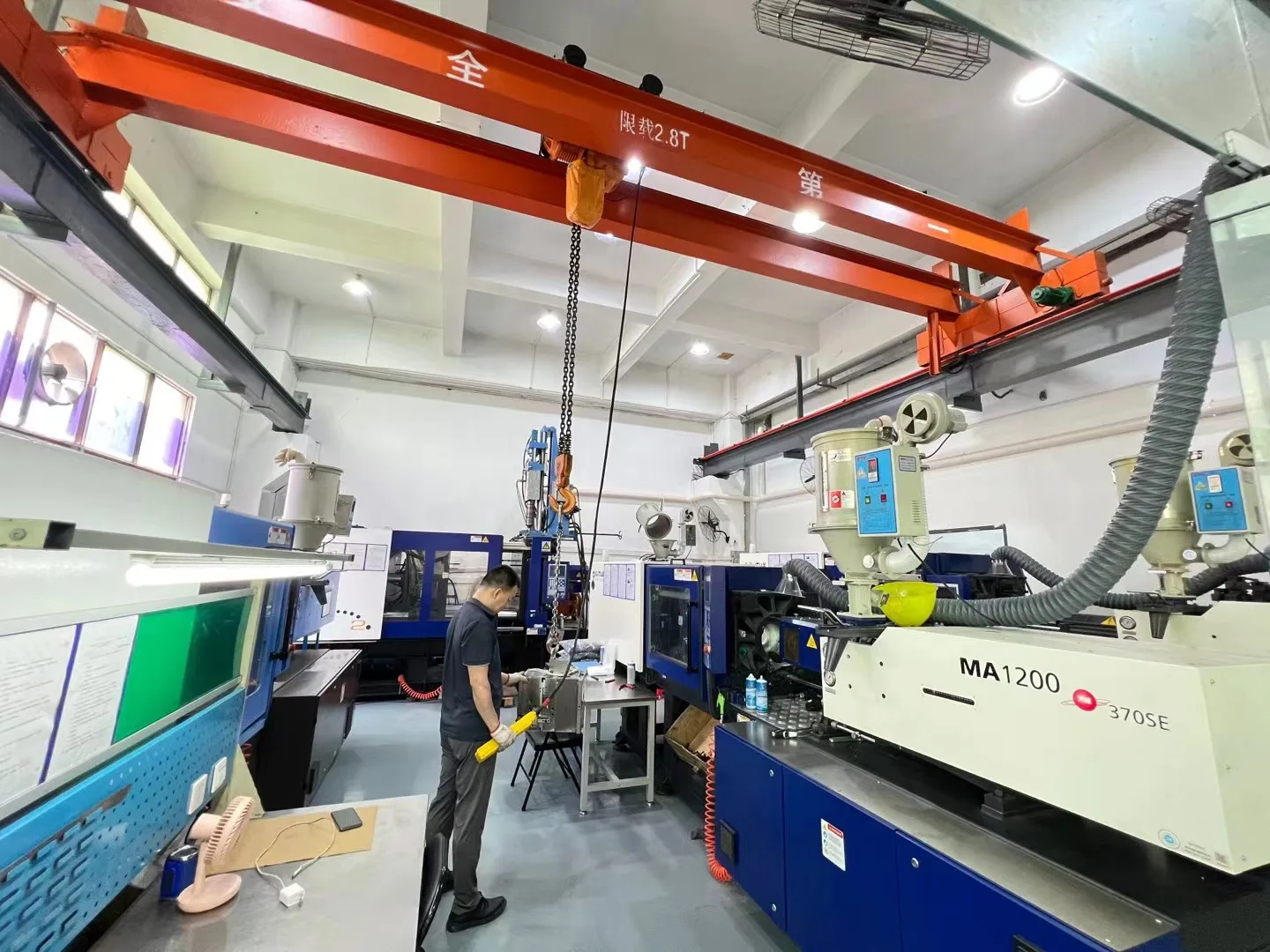
WOKE Molds builds the mold, molds the parts, inspects and ships them from our own factories. Our team brings more than 15 years of mold-making experience.
Our Shenzhen plant runs 41 presses from 30 to 380 tons and is certified to IATF 16949 and ISO 9001. Engineering progress, insert handling and inspection planning are built around the finished-component requirements.
Plan the whole supply scope
Insert molding adds hardware handling and interface controls to a conventional molded-part quote. Separate the one-time project scope from the recurring part cost.
Tooling and insert-locating details, protected shutoffs, any project-specific fixtures, trial scope and the agreed validation activities.
Resin and inserts, loading labor, molding cycle, inspection and packing. Actual cost depends on order size, cavity plan and handling requirements.
Lifetime cost depends on annual demand, order lot, cavity plan, loading and yield. Delivery timing depends on approved design, resin and insert availability, tooling, validation, production scheduling and shipment. MOQ is set by project; quote basis can be EXW, FOB or DDP after destination and shipment details are confirmed.
Common procurement questions
No. This page concerns plastic injected around a pre-positioned metal component. Metal injection molding uses metal powder and binder to form metal parts; it is a different process.
This page is for sourcing insert-molded plastic components. Buyers looking only for custom tooling can review the separate Insert Injection Molds page.
Share the application, candidate resin family and service conditions. The exact grade still needs to be selected and confirmed before the design and quotation are finalized.
Include the insert drawing and revision, material and finish, critical dimensions, lot identification and packaging details. Also clarify expected quantities and ownership of any shortages or revisions.
No single MOQ applies to every project. Tooling, insert sourcing, loading and production economics vary, so quantity and repeat demand are reviewed with the part scope.
Retention depends on the insert, resin, molded section, loading direction and test method. Provide the functional requirement so a suitable application-level acceptance test can be discussed.
Not automatically. Insert type, boss access, resin response, geometry and production sequence differ. Compare the requirements and validate the chosen approach for the part.
Not by default. If the assembly needs a seal, specify the leak requirement, mating design, exposure and verification method for project review.
A change in insert geometry, alloy, plating or resin grade may affect fit, flow, shrinkage or function. Identify proposed changes before ordering so the impact and any needed revalidation can be reviewed.
Start with the available CAD model or drawing revision. You can email files directly to peter@wokemolds.com; add insert specifications and key requirements as they become available.
Start with what you have
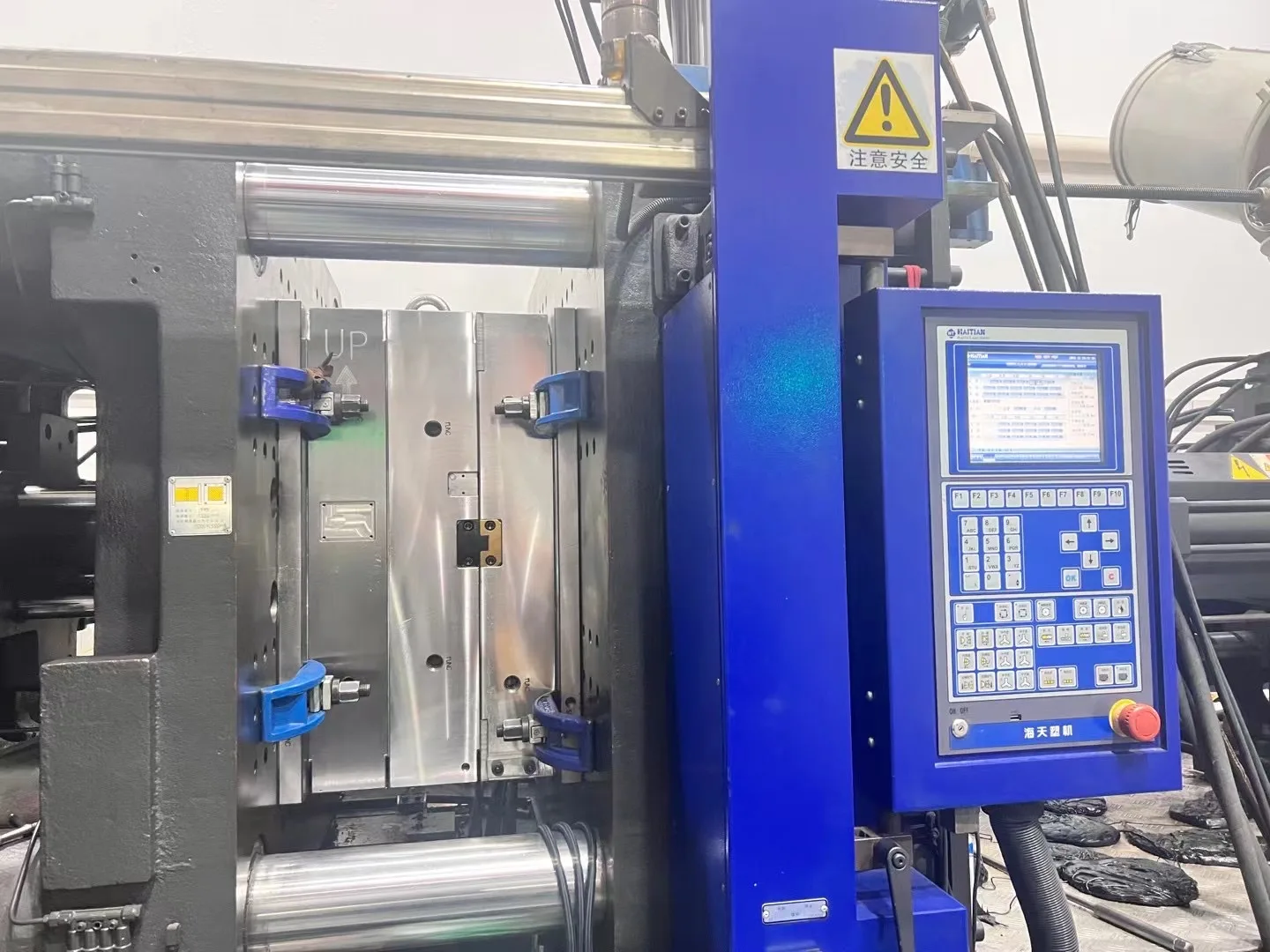
Share your drawing or CAD and the role of the metal feature. Add the resin grade, insert specification, demand and acceptance needs when known. That gives the team a useful starting point for discussing the complete component.