
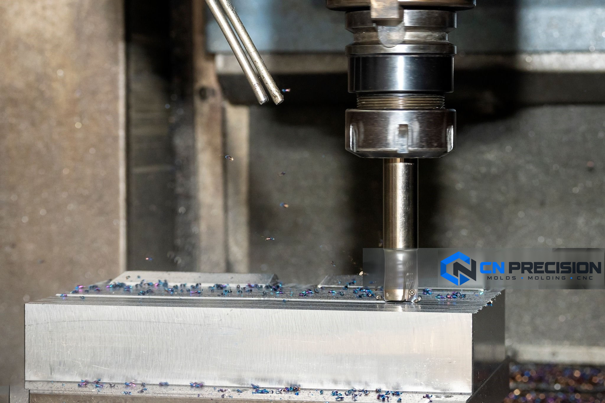
Plates, brackets & mounting faces
Flat faces, slots and hole patterns suit equipment mounts and automation interfaces. Identify the face that seats in the assembly and the dimensions that locate the connected parts.
5 axis CNC machining services · Dongguan, China
5 axis CNC machining services and 3-axis milling for aluminum, stainless steel, titanium and brass parts, from prototypes to production. WOKE Molds mills, finishes and inspects parts to your drawing in our own workshop.
3-axis and 5-axis milling in our Dongguan workshop, with project-specific inspection.
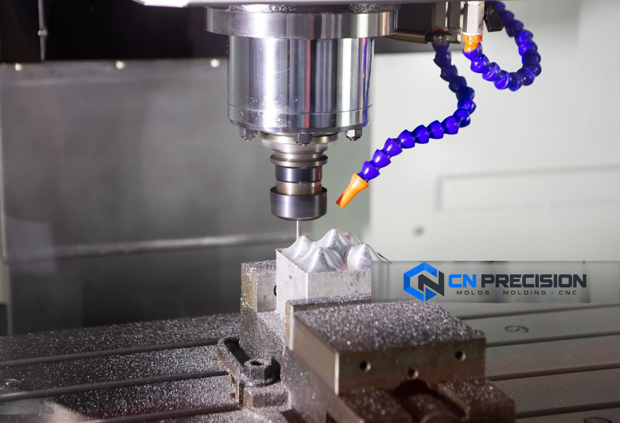
Recognize your geometry
CNC milling removes material with rotating cutters to form prismatic and contoured features. The right starting point is the job each feature performs.
Flat faces, slots and hole patterns suit equipment mounts and automation interfaces. Identify the face that seats in the assembly and the dimensions that locate the connected parts.
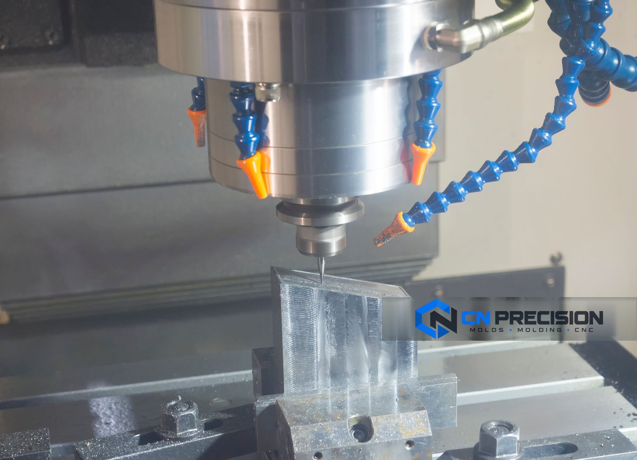
Enclosures and nested components combine internal access with outside fits. Pocket depth, corner clearance, wall support and sealing or cosmetic surfaces should be considered together.
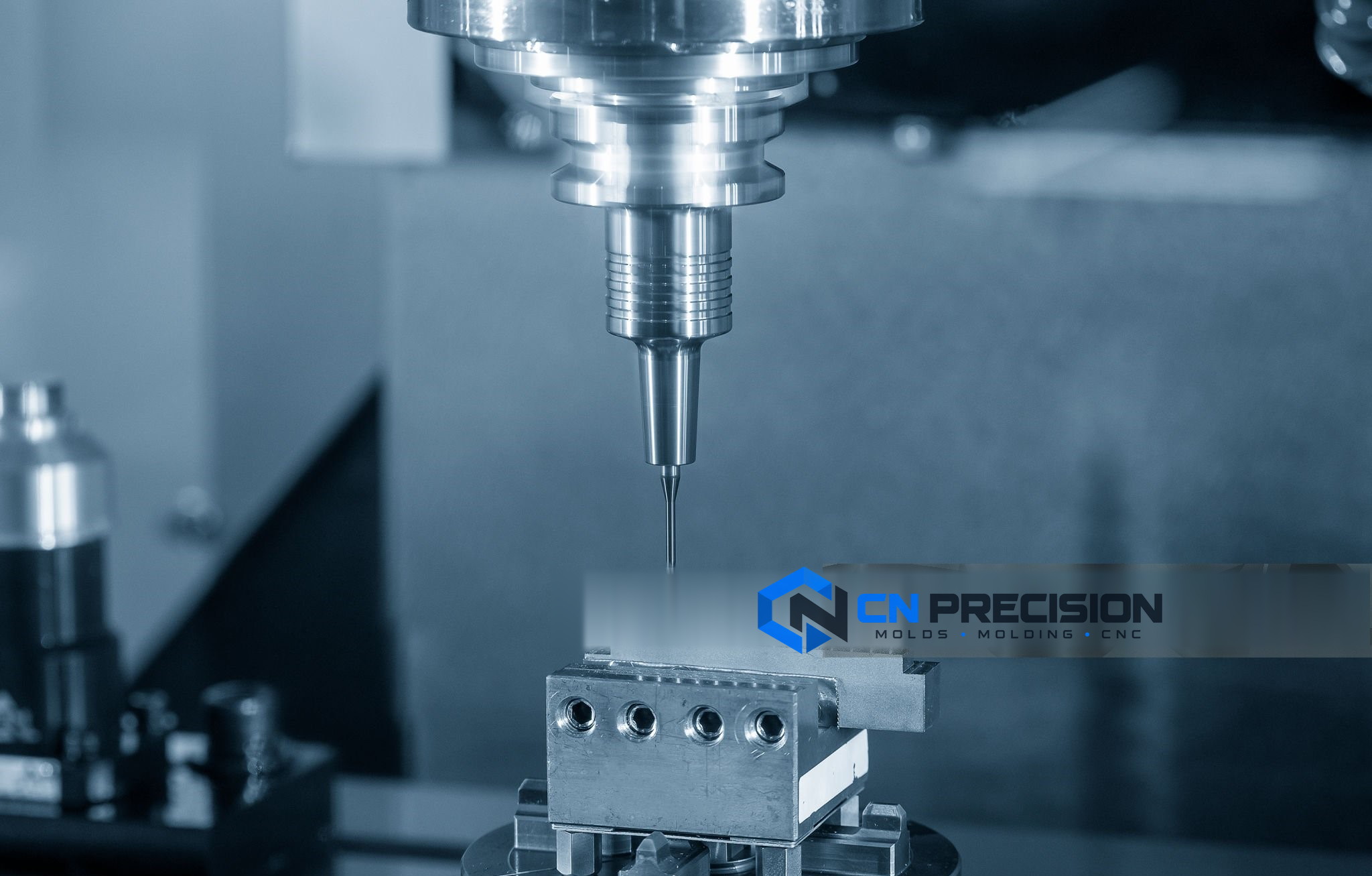
Locating features, small openings and angled interfaces can demand careful access and inspection. Define what locates, clears, clamps or mates, rather than making every feature equally critical.
Process views illustrate the feature discussions above. For instrument, automation and equipment components, the application defines the function, material and acceptance requirements.
Choose by access
3-axis and 5-axis capability provide different ways to reach a feature. More axes alone do not establish tighter tolerance. Access, workholding and the relationships between faces drive the proposed route.
Select the geometry closest to your part. The route remains subject to drawing review.
Geometry → process choice
For plates, pockets, slots and hole patterns where the cutter can reach the geometry, 3-axis milling is a sensible starting point. Additional orientations may still be needed for side or underside features.
Call out the relative position of opposing holes, seating faces and mating features. A part that looks simple may need careful datum transfer between setups.
Geometry → process choice
Indexed machining reorients the part or tool between cuts, then machines at a fixed orientation. It can help access angled holes and several faces; the setup strategy depends on clearance and feature relationships.
No. Indexed positioning and simultaneous multi-axis cutting are different routes. We review the setup and cutting strategy against your geometry, including the orientations and access each feature needs.
Geometry → process choice
Curved surfaces and changing approach directions need a review of cutter reach, holder collision, surface requirements and workholding. The suitable route may involve several orientations or a more involved multi-axis strategy.
Identify functional surfaces and required finish rather than assuming every freeform face needs the same treatment. A complete model plus drawing callouts helps define what must be machined and verified.
Milling, turning, or both? Milling is a natural fit for flats, pockets and multi-face features; turning suits geometry organized around a rotational axis. A part with both types of feature may need a combined route. Share the complete part rather than choosing from its name alone.
Design for the actual cut
A useful design review connects a requirement to tool access, support and a practical acceptance check. Avoid treating a single minimum dimension as a universal rule.
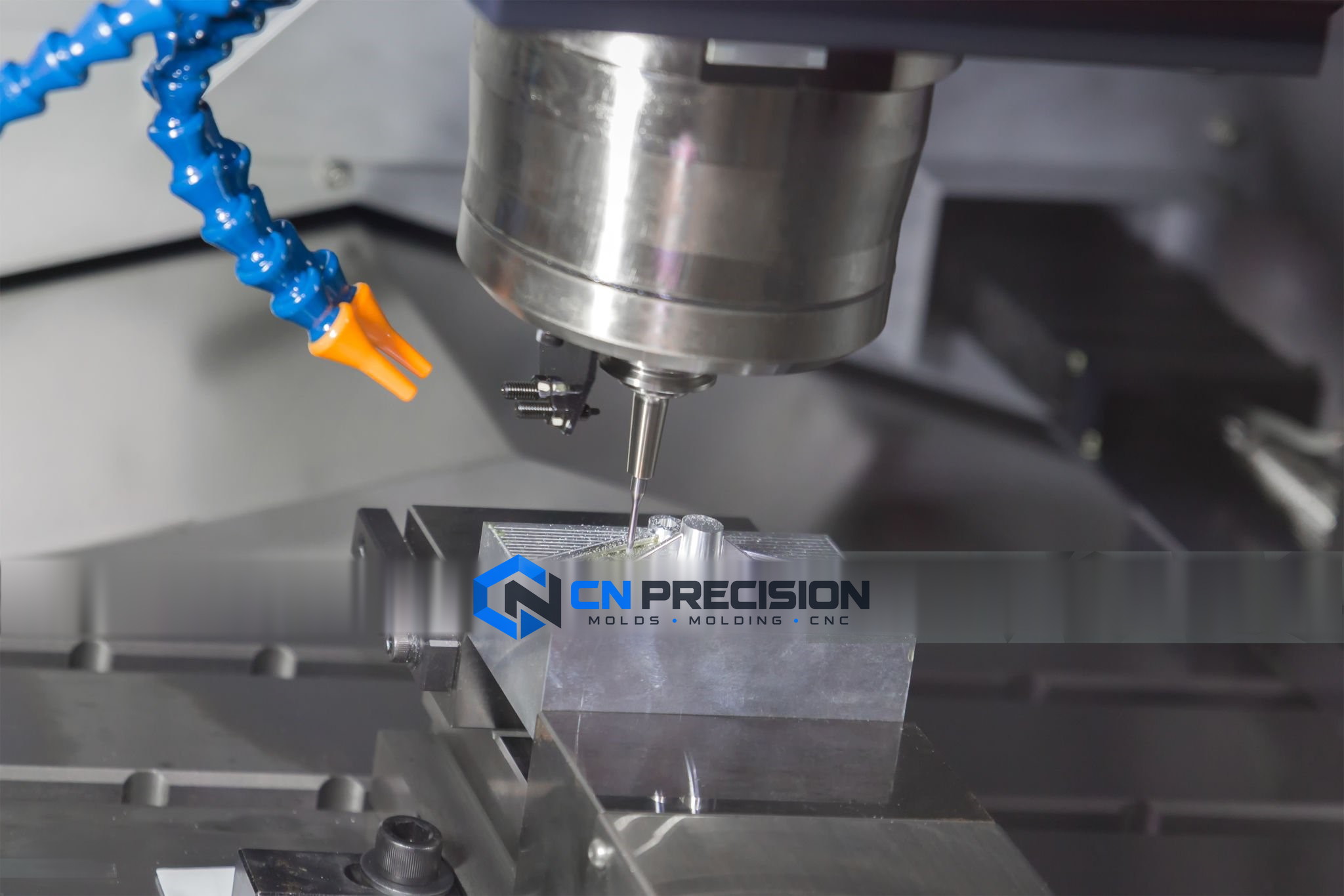
Depth and corner radius must be reviewed together. A deep, narrow pocket can require a longer, less rigid cutter; the holder also needs clearance. Send the full pocket geometry and identify whether a larger radius, wider opening or reduced depth is functionally acceptable.
An ordinary rotating end mill leaves a radius at an internal vertical corner. If a rectangular item must fit, a corner relief or a change to the mating part may provide clearance. Identify a truly sharp requirement early because it may require another operation.
Height, material, nearby support and clamping matter as much as thickness. Cutting or holding forces can move a wall during manufacture. Mark functional wall dimensions and acceptable holding areas; additional support, a revised sequence or a geometry change can then be evaluated.
Provide hole size and depth, through or blind condition, thread designation, pitch and required fit or class. Separate usable thread depth from total blind-hole depth. Deep reach, intersecting holes and treatment inside threads may change tooling and inspection needs.
Check the whole tool and holder path, not only the cutting tip. Recesses behind a lip or features blocked by another wall may need special tooling, another orientation or a design change. State which hidden surfaces are functional and whether the part can be split.
A general request to deburr may not describe a sealing edge, electrical contact, sharp locating corner or visible face. Identify where an edge break is required, restricted or dimensioned. Cross-hole burrs and protected threads deserve explicit attention in the acceptance plan.
Material follows function
Start with load, operating environment, temperature, wear and appearance. WOKE Molds reviews the following material families against geometry, sourcing and acceptance requirements.
| Material family | Start with the part’s job | Confirm before quotation |
|---|---|---|
| Aluminum | Lightweight housings, plates and fixtures; consider stiffness, corrosion environment and appearance. | Name the alloy and temper. Check available stock form and whether anodizing or a cosmetic color match is required. |
| Stainless, carbon & tool steel | Strength, wear, temperature or corrosion needs depend on the specific grade and condition. | Define grade, hardness or heat-treatment state and treatment sequence. Distortion, machining effort and final acceptance need review. |
| Copper & brass | Electrical, thermal or mechanical functions may point to different alloys. | Specify conductivity or other essential properties through the named grade; confirm stock, burr-sensitive features and compatible plating. |
| Titanium | Use where the application justifies the chosen grade and its particular properties. | Identify grade and stock condition. Tool access, heat during cutting, material cost and documentation can influence the route. |
| Engineering plastics | PEEK, POM and nylon are available for project review; grade and conditions govern suitability. | Define service temperature, moisture exposure and measurement state. Stress release and dimensional behavior differ from metal parts. |
Can a plastic part keep the metal prototype’s tolerances? Do not assume so. Polymer grade, temperature, moisture and residual stress influence dimensions. Define the measurement and service conditions for critical fits so the material and machining approach can be evaluated.
Surface & final condition
When is a dimension accepted? State whether the requirement applies as machined, after heat treatment, after coating or in an agreed conditioned state.
Surface roughness is a measurable texture requirement; a uniform cosmetic appearance is a separate acceptance question. Specify each where it matters.
| Finish discussion | Define the purpose | Protect the final requirement |
|---|---|---|
| Aluminum anodizing / hard anodizing | Wear, corrosion or appearance requirement, alloy/temper and specified treatment. | State final fits, coating requirement, cosmetic faces and masking. Color and appearance depend on alloy and preparation. |
| Compatible metal plating / black oxide | Nickel, chrome or zinc plating, or black oxide, where suitable for the substrate and function. | Specify treatment and acceptance basis. Review coating allowance, contact surfaces, threads and any relevant post-treatment requirements. |
| Stainless passivation / electropolishing | Surface treatment appropriate to the grade and exposure. | Separate corrosion or cleanliness requirements from cosmetic expectations. Review dimensional effects and protected features. |
| Blasting / paint / powder coating | Texture, color and external protection on a compatible material. | Identify visible zones, accepted appearance, masking and assembly fits. Coating thickness and coverage can affect clearances. |
| Laser marking | Part identification, revision, logo or lot information as specified. | Define content, location, legibility and protected surfaces. Confirm whether marking occurs before or after the selected finish. |
For aluminum, the Aluminum Anodizers Council reference guide explains why alloy and dimensional buildup belong in the finishing discussion.
Quality begins in the definition
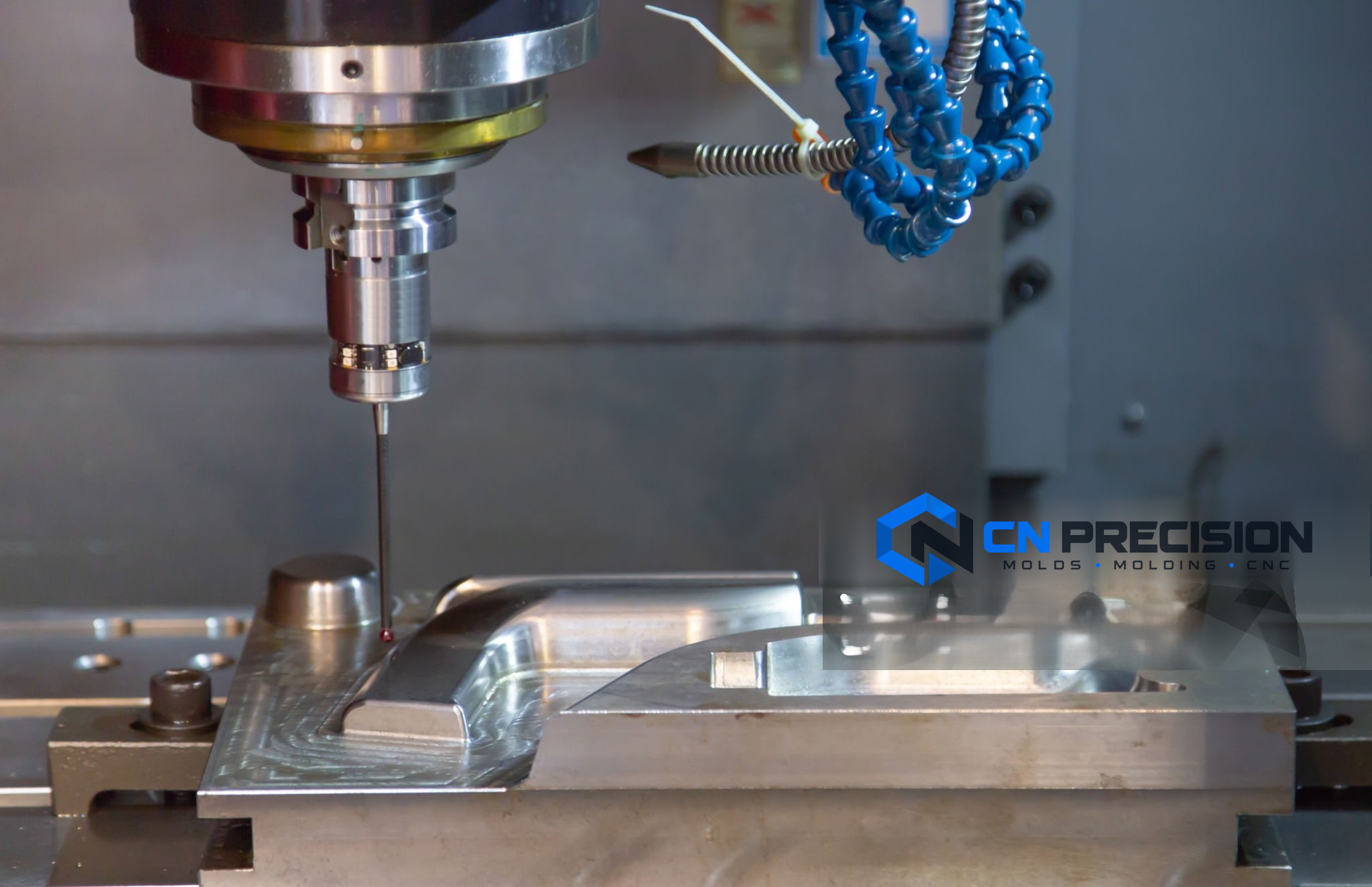
What tolerance can you hold? The useful answer starts with your drawing, material, geometry and final condition.
For a mounting face and hole pattern, identify how the assembly seats and locates first. The inspection alignment should represent those functional references. Neither a machine’s stated accuracy nor a measurement photograph establishes a universal part tolerance.
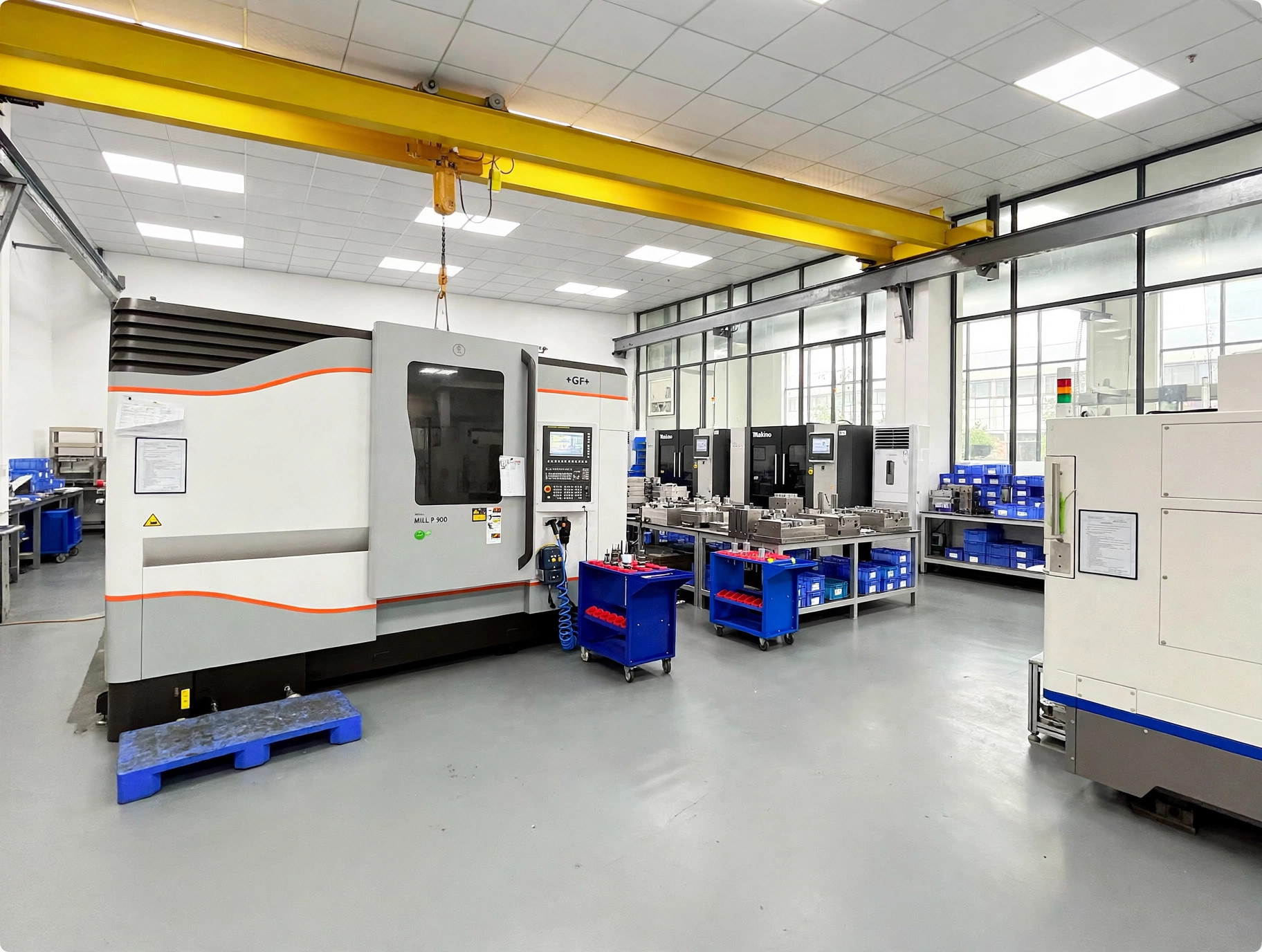
In-house machining
WOKE Molds brings a team with more than 15 years of experience to custom-part projects. The service covers metal and engineering-plastic parts, from prototypes and small or medium batches to volume production.
Our factory in Dongguan runs a Makino D500 5-axis machining center, Makino V33i and F5 high-speed machining centers, YCM and Qiaofeng machining centers, wire and sinker EDM and Okamoto grinders. The setup is selected against your geometry, material and acceptance needs.
We connect the machining route with material sourcing, finishing and critical-characteristic inspection. Part size and access are reviewed from the complete geometry, rather than inferred from nominal machine travel.
From stock to shipment
The route can change with the geometry, treatment and quantity. These are manufacturing stages to define during project review.
Before manufacture: clarify open drawing issues for quotation, then release the agreed specification, commercial scope and acceptance requirements. A quote assumption should not silently become a production instruction.
Confirm the specified material condition and suitable stock. Establish the reference faces and holding approach that support later feature relationships.
Remove bulk material while considering support, tool reach and distortion risk. Extra orientations or treatment stages depend on the geometry and material.
Machine the required faces, pockets, bores and threads to the agreed sequence. Preserve the datum relationships needed for assembly and inspection.
Address specified edges and burr-sensitive intersections. Coordinate heat or surface treatment, masking and protection of critical or cosmetic features.
Check the agreed characteristics in the defined state, complete the requested records and confirm identification and packing for the order.
Engineering examples
Illustrative requirements, engineering trade-offs and checks to resolve during a manufacturing review.
RequirementA rectangular mating insert must clear the corners at the bottom of a deep pocket.
Trade-off & validationReview cutter reach and corner relief, or revise the mating insert. Validate the resulting clearance and the required pocket dimensions.
RequirementThe enclosure must retain its assembly shape, with a visible outside face.
Trade-off & validationReview support and permitted clamping areas alongside wall geometry. Check functional dimensions in the agreed state and define acceptable cosmetic evidence.
RequirementA bore must fit its mating component after treatment.
Trade-off & validationAgree final-condition acceptance, coating allowance and any masking. Verify the finished fit rather than accepting the pre-treatment bore alone.
Cost & quotation
Why does unit price change with quantity? Programming, setup and fixtures can be distributed across more parts. Stock, cutting time, finishing and inspection still matter. Quote the prototype and repeat quantities you actually expect to buy.
To reduce effort, discuss nonfunctional tight callouts, inaccessible details or cosmetic requirements that exceed the real need. Preserve the characteristics that control function.
Repeat production
For a repeat order, confirm part number, revision, material condition, finish and acceptance requirements against the previous approved scope. A new stock source, heat treatment, drawing revision or coating requirement may need another review.
State release quantities and expected order cadence. For a repeat program, agree which fixtures, programs and production or inspection records need to remain available, and the arrangements for retaining them.
Identify lot or batch documentation where required. Keep any agreed substitution and revision approval visible to both purchasing and engineering.
Practical answers
Start with the information you have. A clear account of what is known, what is critical and what remains open makes the next discussion more useful.
A model can start the review. Add a drawing or clear callouts for tolerances, threads, surface requirements and other details not fully defined by geometry. Missing information must be resolved before production release.
State the intended units clearly and keep the model, drawing and notes consistent. Any conversion, rounding or conflicting unit information should be clarified during review.
A single prototype can be assessed. The quotation and schedule depend on the geometry, stock, setup, finish and inspection requirements.
Quantity is reviewed with the part and manufacturing scope. Share the initial order and likely repeat demand so material purchasing, setup and treatment batches can be considered.
Yes, 5-axis milling is part of the supported capability. The suitable setup and cutting route are reviewed from the geometry. We confirm the required orientations, tool access and sequence for the individual part.
Describe the available sample and any drawings or measurements. Review is needed to establish a controlled specification; a worn or incomplete part alone may not define the intended dimensions and function.
Yes, identify the certificate type, grade, lot traceability and any other material evidence required in the RFQ. Availability and document scope need confirmation for the selected material and order.
Raise this at inquiry. Stock condition, dimensions, identification, documentation, incoming acceptance and responsibility for unsuitable material must be agreed before treating it as an approved input.
Provide the feature-specific callout and final acceptance state. Capability is reviewed against geometry, material, access, process and measurement; no single tolerance or roughness value applies to every part.
Provide the sample or specification and identify the visible surfaces and acceptable variation. Material grade, preparation and treatment affect appearance, so the achievable acceptance basis must be agreed.
State the required receiving date and destination. Stock, specification approval, setup, treatments, inspection and transport must be checked before a schedule can be confirmed.
EXW, FOB or DDP can be scoped by project. Share the destination and receiving requirements so packing, transport, duties and import responsibilities are explicit in the quotation.
Start with your part
Share the geometry and what the part must do. Add your material, quantity and acceptance needs when known; open details can be clarified during review.