
Insert Injection Molds
Integrate functional metal features into molded parts with tooling built around repeatable insert location, protected surfaces and practical loading.
WOKE Molds designs, machines, fits and trials the mold in our own factory in Chang’an, Dongguan, and can run series production in our Shenzhen molding plant.
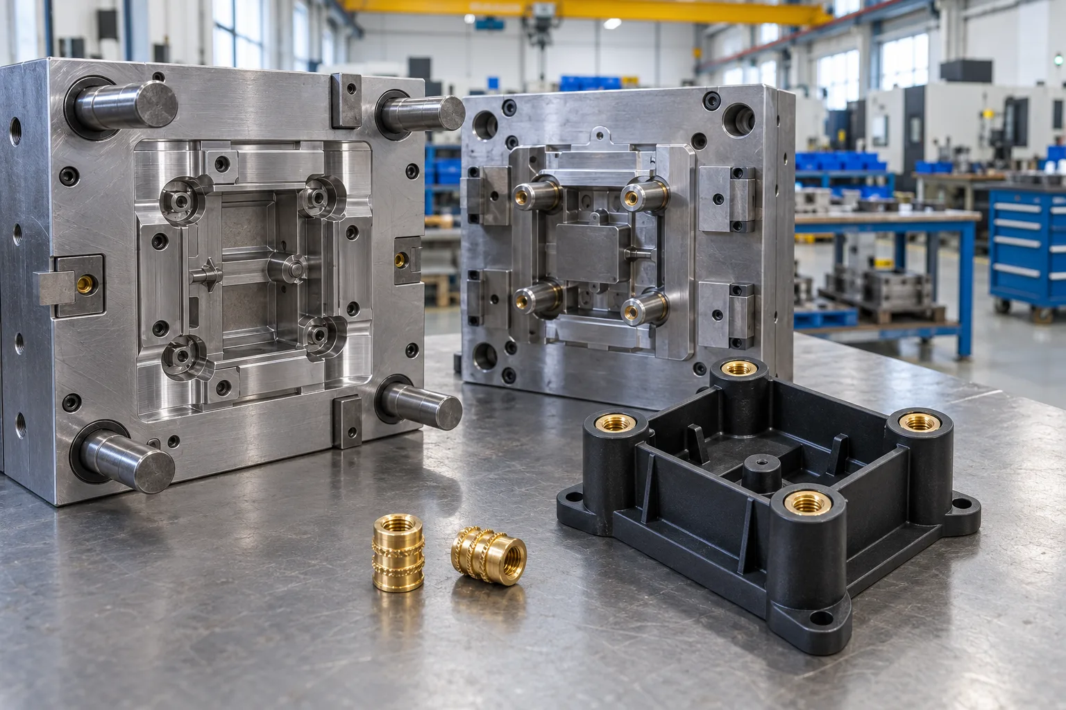
Tooling for Threaded Inserts, Contacts and Sleeves
Threaded inserts, contact carriers and structural sleeves each create different locating, sealing and loading decisions. Pins and stamped carriers can also be reviewed where their geometry, supply variation and loading method suit the project.
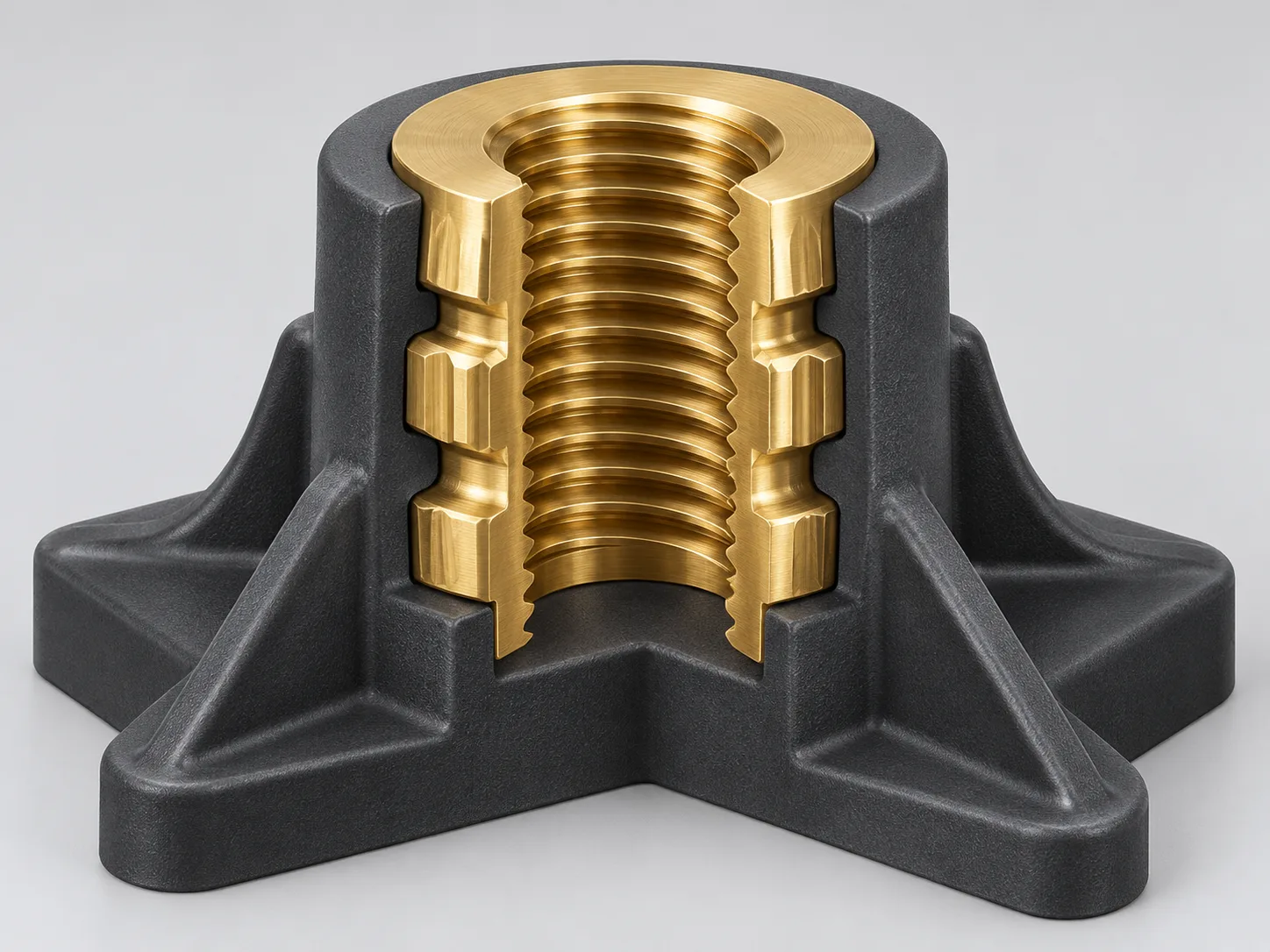
Threaded fastening assemblies
A brass insert in an equipment housing provides a reusable screw joint. The tool must establish a repeatable locating datum, seal the thread or exposed face, and support the insert against filling force without marking a functional surface.
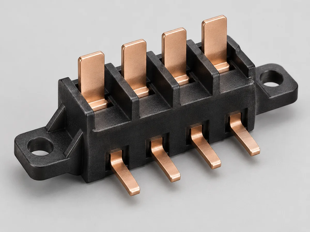
Terminal and contact housings
A stamped terminal carrier positions conductive features inside an insulating body. The decisive tooling questions are contact location, shutoff around exposed metal, gate and weld-line placement, and how orientation will be verified before the mold closes.
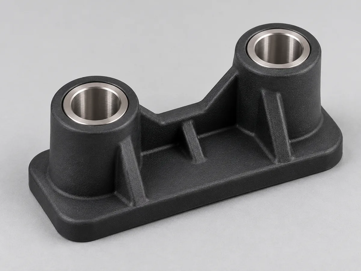
Sleeves and reinforcement brackets
A steel sleeve or bracket carries a bearing, mounting or reinforcement load while plastic forms the surrounding geometry. Tooling review focuses on support at both ends, resin access, stress around the boss and a release path that does not distort the assembly.
What Insert Molding Can Add to Your Product
A molded-in insert is a preformed component placed in the mold before injection and retained in the finished part. The mold must hold it against filling pressure while controlling which areas are encapsulated, exposed or sealed from resin.
Part geometry, insert tolerances, resin behavior, expected loads and receiving equipment shape the tool concept. Define the loading and acceptance requirements alongside the finished-part drawing.
Integrate assembly
Molding can remove a later insertion step when insert supply, loading time and fault handling support the target volume.
Create reusable interfaces
Threaded inserts or bearing surfaces can carry repeated assembly loads when the surrounding plastic and retention geometry are designed for the real load case.
Locate functional elements
Contacts, pins and components can be held within molded geometry, provided datums, sealing and fill behavior maintain the required position.
Use metal selectively
Metal remains only where conduction, wear or load transfer needs it; this works best when thermal movement and local plastic stress are reviewed together.
Match the Tool to Your Application
Each application sets a different priority: assembly strength, contact position, sealing or wear. We connect that function to the locating, molding and acceptance requirements.
Equipment and appliance housings
Reusable fastening points may support covers, handles or service panels. Boss support, cosmetic surfaces and repeated tightening drive the retention and validation plan.
Connector and terminal carriers
Contacts must remain exposed where they mate and insulated where the plastic separates them. Position, flash control, weld lines and electrical checks become linked decisions.
Industrial sensor and instrument housings
Inserted bushings, sleeves or terminals may establish mounting, sealing or signal interfaces. Gate location, dimensional conditioning and any leak or electrical test must be defined.
Mechanical supports and bushings
Metal can provide a wear or load-transfer surface inside a molded bracket. Support during filling, concentricity, plastic stress and ejection direction shape the tool concept.
How the Insert Molding Cycle Works
Insert count, orientation and loading time affect practical cavity count and cell sizing. Presence detection does not replace good seating; it verifies that the planned condition exists before molding.
Present the insert
Orient, clean and seat each insert; verify presence and direction where required.
Seat and seal
Tool features support the insert and shut off protected threads, faces or contacts.
Control movement
Gate and process choices manage force, weld lines, air traps and local encapsulation.
Release safely
Cooling and ejection must release the hybrid part without boss stress or insert displacement.
Confirm function
Check seating, protected surfaces, critical molded dimensions and agreed functional characteristics.
Design Around the Insert and Its Function
The insert establishes real datums, contact surfaces and variation that the mold must accommodate. Review starts with the controlled insert specification and, where available, representative samples to check the supplied condition.
- Locating datums and toleranceIdentify the surfaces that actually seat and orient the insert, review accumulated tolerance, and compare drawings with sample condition, coating and burr limits.
- Retention and load caseDefine how the plastic supports the insert and which in-service loads matter. Geometry, material, mating support and test method all affect performance.
- Shutoffs and protected surfacesMark threads, electrical contacts, sealing faces and cosmetic areas that must remain free of resin, then plan shutoff contact and wear management around them.
Control the Features That Decide Part Quality
Insert molding risks interact. A gate change may reduce insert deflection but alter weld lines or packing; greater shutoff contact may improve sealing but mark the insert or increase wear. Tool decisions therefore connect the issue, the design response and the planned validation.
Positioning and deflection
Locating support, accumulated insert tolerance, gate position and filling balance are reviewed together; trials check seating and critical position.
Protected threads and faces
Shutoff geometry, insert variation and serviceable wear pieces control resin at threads, contacts and sealing surfaces.
Anti-rotation and pullout
Knurls, undercuts or other retention features are matched to load direction, surrounding support and an agreed representative test.
Boss stress and sharp edges
Local wall, radii, metal edges, resin shrinkage and thermal movement are reviewed to reduce concentrated stress around the insert.
Gate, vent and weld lines
Flow direction should limit insert movement while placing weld lines and vents away from functionally sensitive regions where practical.
Cooling, ejection and wear
Cooling balance, release direction, ejector support and replaceable contact details protect the part and keep routine tool service practical.
Manual, Fixture-Assisted or Automated Loading
Manual, fixture-assisted and automated loading each fit different combinations of insert feedability, orientation, cavity count, access, cycle demand and changeover frequency.
Manual loading
Useful when insert varieties, lower cavity counts or changeovers favor operator flexibility. The tool still needs safe access, unmistakable orientation and a practical way to confirm complete seating.
- Review reach, visibility and loading sequence
- Reduce opportunities for reversed or missed inserts
- Consider operator interaction with the press cycle
Fixture-assisted loading
A removable nest or carrier can improve orientation and multi-insert placement without committing immediately to a fully automated cell.
- Define transfer datums and confirmation
- Keep loading and removal ergonomic
- Plan fixture variation and maintenance
Automated loading
Appropriate when consistent feeding, placement and cycle integration justify a dedicated cell concept. Insert presentation and pickup reliability must be proven alongside the mold interface.
- Define datum transfer from feeder to cavity
- Plan end-of-arm access and release
- Coordinate recovery from jams or bad orientation
Agreeing these inputs before mold release helps prevent arrival mismatch. HASCO, Meusburger or DME standards can be followed when required; original branded components are used when specified.
Resin and Insert Material Options
Material family names are not enough for tooling decisions. The released grades, reinforcement, insert surface condition and functional environment determine what must be evaluated and tested.
| Resin family | Typical insert-molding review | Tooling and validation focus |
|---|---|---|
| ABS, PC and PC/ABS | Housing geometry, boss stress, appearance and the released end-use grade. | PC blends need grade-specific drying and stress review; gate and knit-line location are assessed around the insert. |
| PA6 / PA66, including glass-filled grades | Conditioning and drying; fiber orientation and directional shrinkage for reinforced grades. | Wear, gate direction, local stress and post-mold dimensional checks are set for the selected grade. |
| PBT | Exact grade, drying requirement, electrical or dimensional role and insert geometry. | Gate position, warpage and local encapsulation are reviewed against the chosen grade and conditioning plan. |
| PP and POM | Grade, part geometry, shrinkage behavior, boss support and required load surface. | Retention and dimensional stability cannot be inferred from the family name; representative assemblies need agreed checks. |
| PPS, PEEK, PPA and LCP | Grade-specific thermal window, filler, service condition and insert stability. | Steel, abrasion, venting, gating and temperature control are matched to the released material grade. |
Metal choices: brass is common for threaded interfaces; steel or stainless can serve bearing, support or corrosion needs; copper supports conductive functions; aluminum may reduce mass but finish and dimensional stability require evaluation. Each combination is project-reviewed. For meaningful acceptance, agree the test part, conditioning, fixture and load method together.
Why Work With WOKE Molds?
WOKE Molds builds molds for international customers in our own factory in Chang’an, Dongguan, with series production in our Shenzhen plant. One team handles engineering decisions, toolmaking, trials, issue closure and delivery.
Released 2D and 3D mold files, key engineering data, customer standards and controlled changes keep approvals visible; weekly photo updates show machining, fitting and trial progress at planned checkpoints.
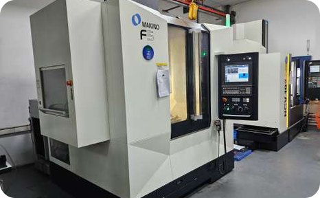
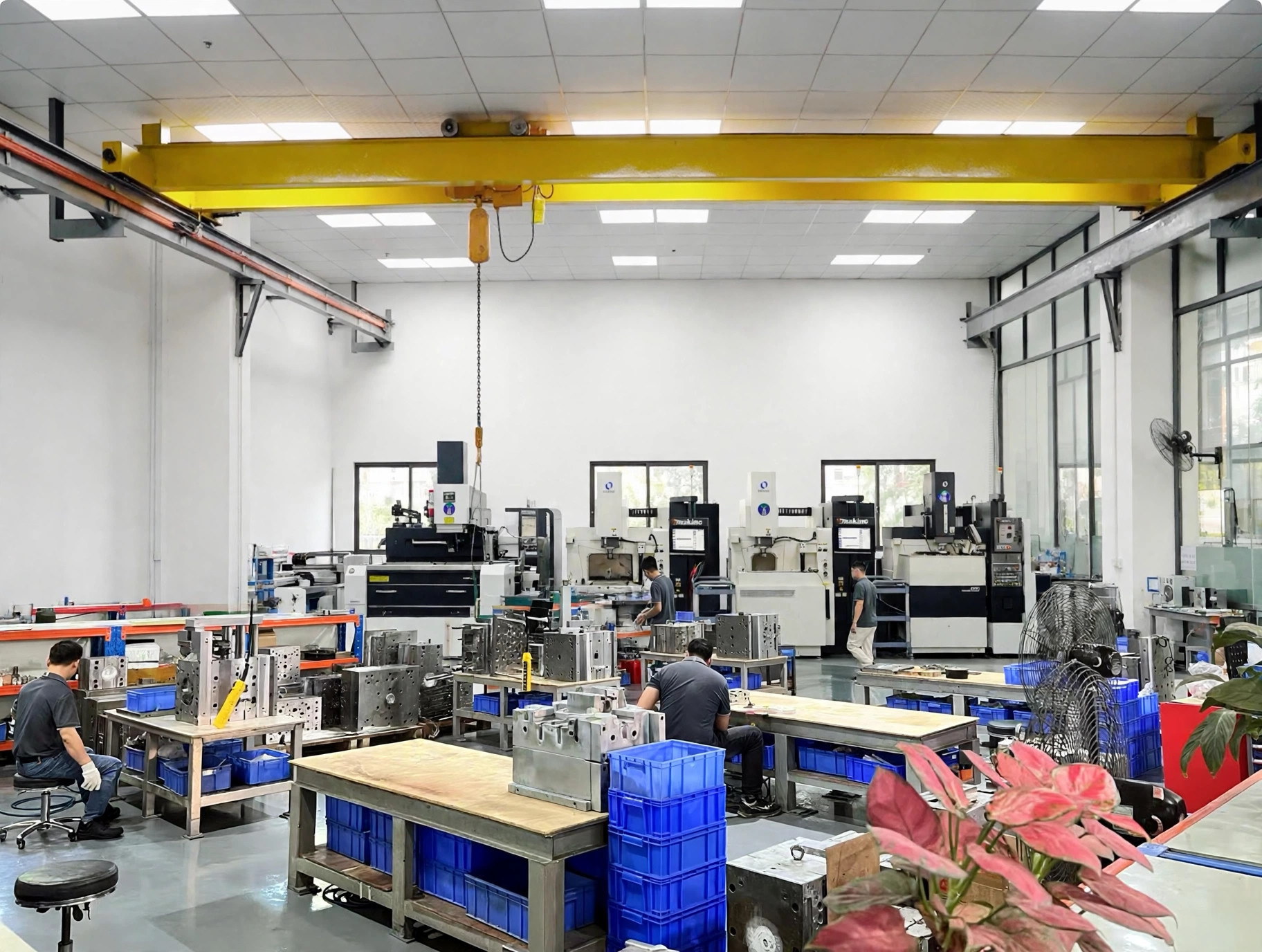
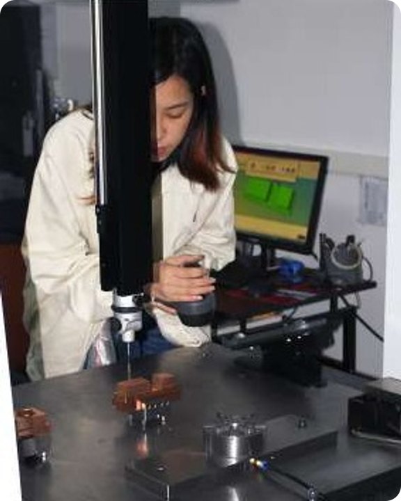
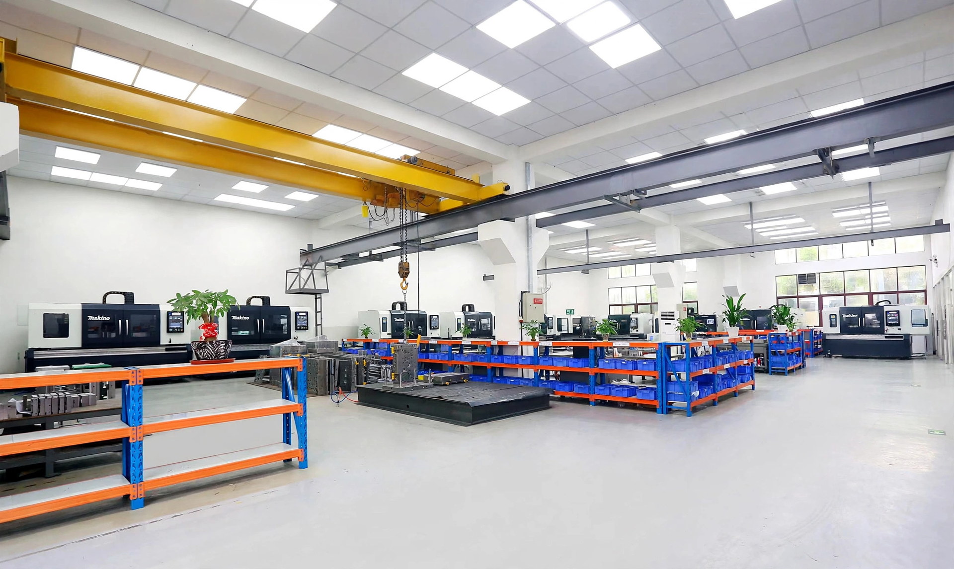
Inside the Tooling Workshop
See machining, mold fitting and dimensional inspection inside the project workflow.
From Drawing Review to Tool Approval
Formal DFM starts after project kickoff. Each phase returns a defined decision or deliverable so changes are controlled before the next commitment.
Engineering Decisions in Context
These worked examples show how a functional requirement becomes a tooling decision and an agreed validation plan.
Threaded housing for repeated assembly
- Requirement
- A service cover is removed repeatedly without relying on a plastic thread.
- Design decision
- Define insert datum, anti-rotation geometry, supported boss walls, protected threads and a gate path that does not push the insert off seat.
- Validation to define
- Conditioned assembly samples, thread gauging and an agreed torque or pullout method using representative mating hardware.
Terminal carrier with stable contact position
- Requirement
- Several contacts must remain exposed, oriented and positioned inside insulating geometry.
- Design decision
- Control carrier datums, shutoffs, filling balance, weld-line location and presence/orientation sensing.
- Validation to define
- Contact position, resin-free mating areas and electrical or functional checks only where specified by the customer.
Inspection Built Around Your Acceptance Criteria
Incoming steel, resin and components are verified to the project specification; machining, EDM, fitting and trial checks build the evidence chain. The agreed documentation can include first-article inspection, dimensional or CMM reports, material certificates and mold trial records.
| Requirement | Method | Evidence to agree |
|---|---|---|
| Insert position and seating | Datum measurement, check fixture or CMM as appropriate. | Critical locations, sampling and report format. |
| Protected surfaces and threads | Visual inspection and agreed thread or profile gauge. | Flash boundary and acceptance limit. |
| Critical plastic dimensions | Measurement after defined molding and conditioning state. | Drawing characteristics and conditioning record. |
| Retention or end function | Agreed torque, pullout, leak or electrical test only when scoped. | Fixture, load direction, sample state and pass criteria. |
| Trial and issue closure | Record material, settings, revision, observations and actions. | Trial report plus approved closure status. |
What Drives the Cost of an Insert Mold?
Tool investment is quoted separately from recurring insert loading and molded-part cost. The drawing package lets us distinguish one-time tooling decisions from each-cycle handling.
Insert count and cavities
More insert positions multiply locating details, loading actions, sensing and recovery paths.
Datums and protected surfaces
Tight position control, thread shutoffs and exposed contacts add fitting and validation work.
Runner, steel and resin
Flow layout, abrasive or high-temperature grades, steel choice and component standard affect build cost.
Loading and validation
Fixtures, loader interfaces, sensors and special functional tests are scoped to the production plan.
Start a Quotation with the Files You Have
An initial review can start with the files and requirements already available. Remaining technical inputs can be resolved during follow-up, while the quotation records what is included in tooling, validation and handover.
Inputs that improve quotation accuracy
- Part definition
- 3D CAD and 2D drawings with critical dimensions, resin grade and functional surfaces.
- Insert definition
- Insert drawings, tolerances, material/coating and samples or supply information when available.
- Production basis
- Demand, preferred cavity count, loading concept, target cycle considerations and changeover needs.
- Receiving equipment
- Press data, mold standard, interfaces and destination requirements if the mold will run at your facility.
Scope to align before order
- Tool definition
- Mold dimensions, cavities, steel and component standards, runner concept and specified interfaces.
- Loading boundary
- Manual access or loader interface, plus the responsibility for feeders, robot grippers, sensors and cell controls.
- Validation and handover
- Trials, samples, agreed inspection or functional evidence, documentation, packing and spare-parts needs.
- Commercial delivery
- Project-dependent timing and agreed EXW, FOB or DDP terms, with dependencies on approvals, materials, components and validation.
Typical mold lead time is 4–8 weeks, confirmed by quotation. Complexity, steel, standard components, finish, validation and customer approvals determine the actual schedule.
Discuss Quotation ScopeA Clear Handover to Your Production Team
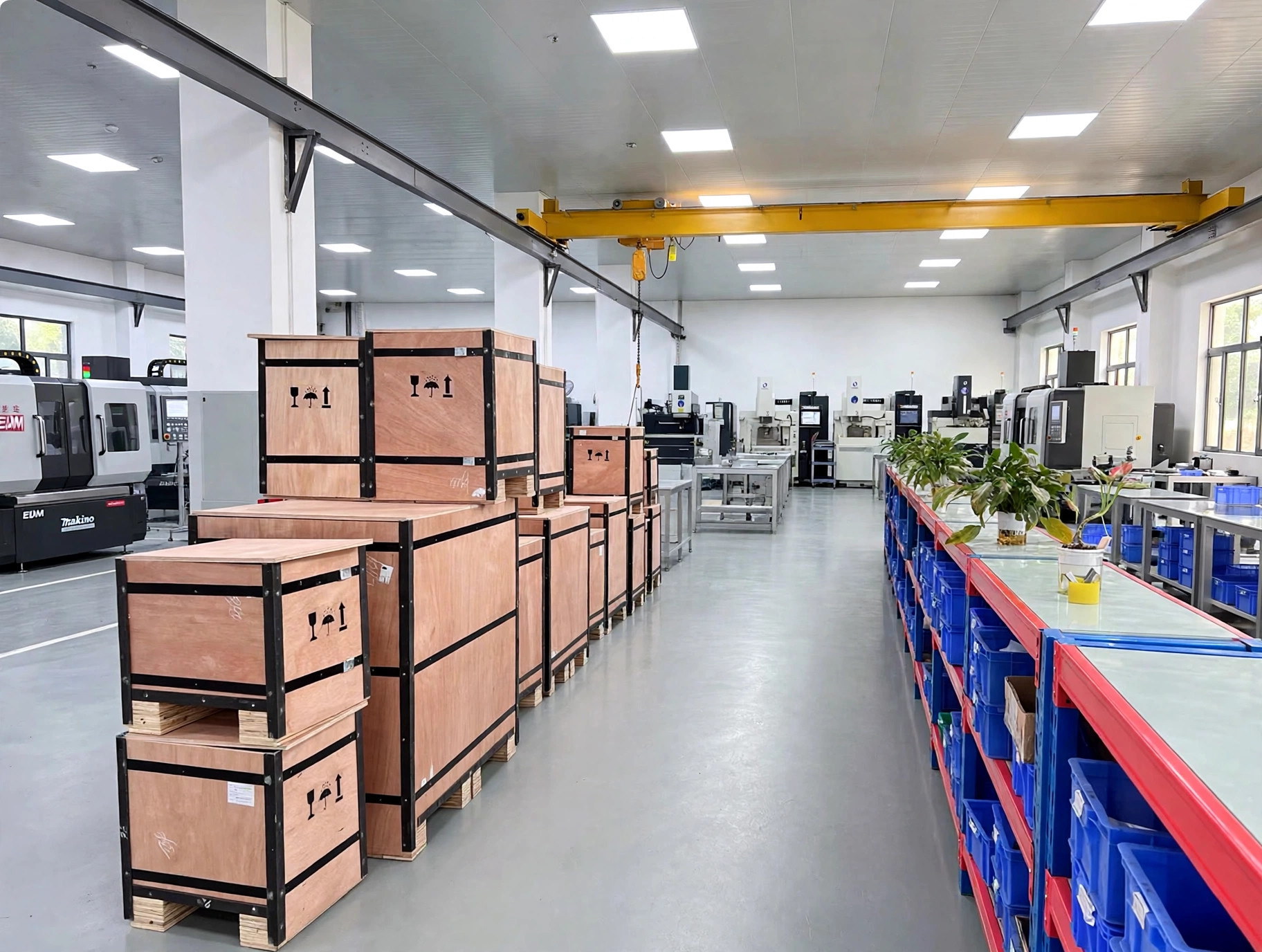
Handover can include released 2D/3D mold drawings, scoped trial and inspection information, agreed spares, utility details and maintenance guidance. The mold receives anti-rust protection, vacuum packing and a wooden case for shipment.
After delivery, remote technical support and issue analysis help your team address start-up or maintenance questions. Spare parts, mold modifications and repair support are arranged to the agreed project scope.
EXW, FOB or DDP terms, destination requirements and shipment responsibilities are confirmed in the project quotation.
Insert injection mold FAQs
Practical answers for drawing review, insert changes, production planning and mold delivery.
Which files are useful for an initial review?
Send the available part and insert 3D models plus 2D drawings. Exact resin, insert material/coating, demand, receiving press and required functional checks are helpful when known and can be completed in follow-up.
What happens if the insert supplier changes after tooling?
Provide the revised controlled drawing and representative samples before production use. Datum size, coating, burrs, edge breaks and tolerance shifts may require a seating, shutoff, pickup or validation review.
Can drawings mix metric and inch requirements?
Yes, when the controlled drawing identifies units clearly. Mold interfaces, insert threads, gauges and receiving-plant standards should be reconciled before design release to avoid conversion ambiguity.
Can electronics or sensors be molded in?
Heat-, pressure- or moisture-sensitive components need a specific review of encapsulation, support, sealing, material exposure and test access. Insert molding is not assumed suitable until those limits are defined.
Why are physical insert samples important?
Samples reveal actual coating, burrs, edge breaks, cleanliness and dimensional variation. Those details influence seating, shutoff contact, automation pickup and whether the tool must accommodate supplier variation.
Can a manual-loading tool be automated later?
Sometimes, but the retrofit should be anticipated. Cavity access, insert presentation, pickup datums, sensor space, robot approach, guarding and cycle logic may otherwise constrain automation or require tool and cell changes.
Do metal inserts always require preheating?
No. Insert material, mass, resin, moisture, surface condition, stress risk and process window determine whether temperature control or preheating is useful. It should be evaluated for the specific application.
How does cavity count affect insert molding?
More cavities multiply inserts, loading actions and opportunities for missed or misoriented components. Cavity count should balance demand, tool and press constraints, feedability, loading time, access and fault recovery.
Can several insert variants share one mold?
Potentially, if the variants preserve reliable datums, shutoffs, loading access and part requirements. Change inserts or interchangeable tool details must also control mix-up risk and changeover verification.
Can you export the mold or produce the molded parts?
Both routes can be discussed, but they are quoted separately. For mold export, receiving-press and local standards matter. For recurring production, insert supply, cell loading, inspection, packaging and demand planning also need alignment.
Discuss Your Insert Mold
Send the part and insert files you have. Resin grade, insert samples, expected demand and receiving-press information help us frame the tooling review.