
Unscrewing Injection Molds
Custom injection mold tooling for controlled release of molded plastic threads, engineered around the actual thread, resin and receiving press.
WOKE Molds designs, builds, trials and ships unscrewing molds from our own factory in Dongguan. The release sequence, drive concept and machine interface are reviewed as one system.
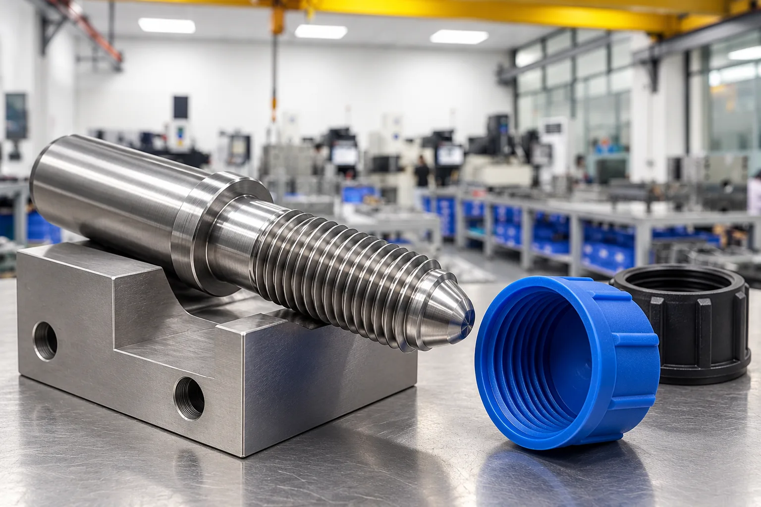
- 15+ years of team industry experience
- Our factory in Chang’an, Dongguan
- Engineering → build → trial → delivery
Tooling for Closures, Connectors and Threaded Collars
One-piece molded threads create different release and inspection demands. Explore the part functions below, then relate the thread geometry to the mechanism and acceptance plan.
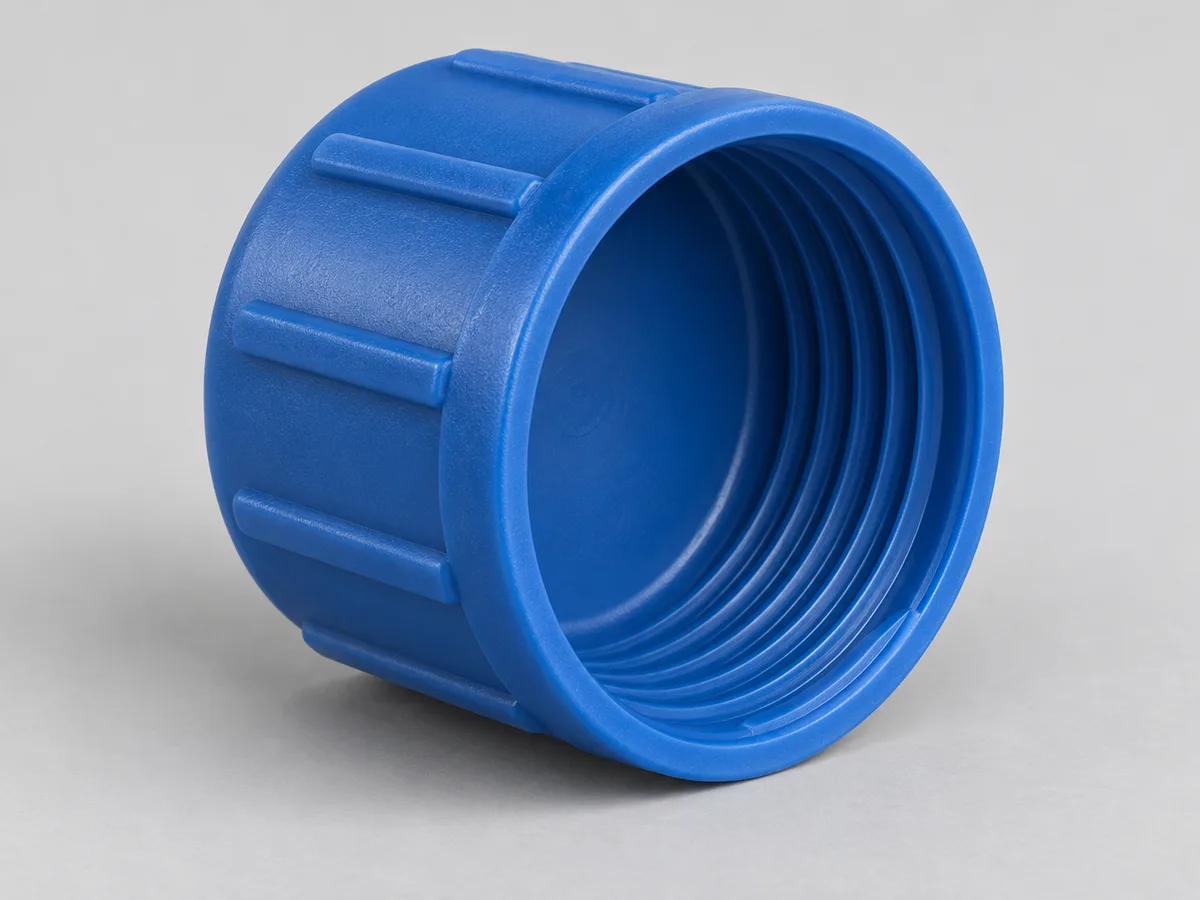
Internally threaded closures
Continuous internal threads need a defined start, engagement and sealing face. The mold must hold the part against rotation while the core clears without unacceptable wall distortion.
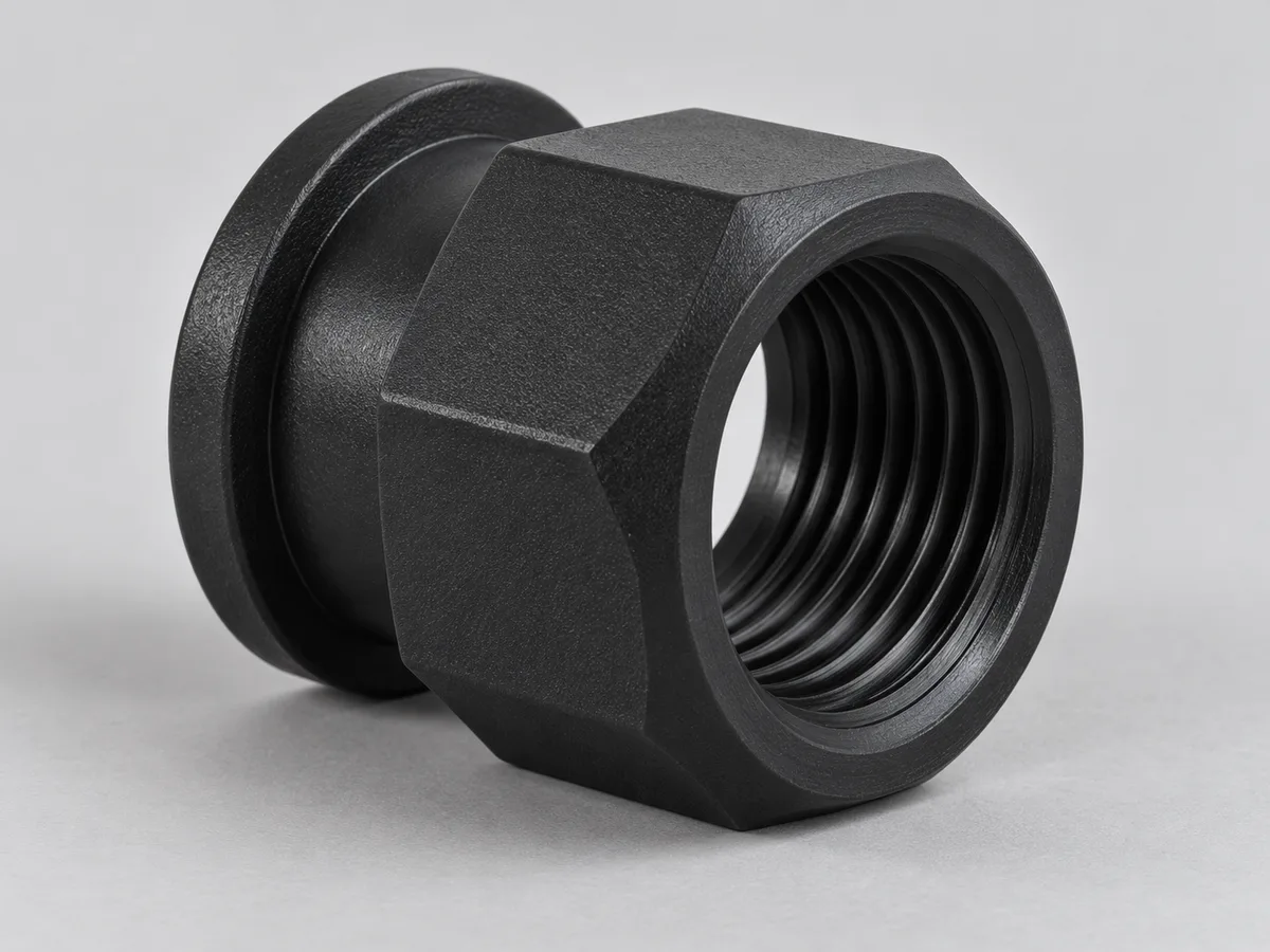
Female connectors and bushings
Functional threads must work with the bore and mating datum. Review engagement, runout, concentricity, anti-rotation reaction and any joint-level leak test as one acceptance plan.
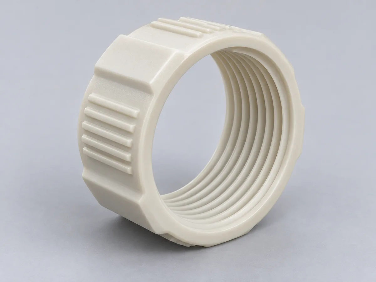
Retaining collars and functional housings
Threaded retainers can use internal or accessible external forms. Parting freedom, witness limits, wall stiffness and release direction determine whether rotational release is justified.
Industrial assembly
Threaded retainers, adjustment elements and housings where repeatable engagement matters.
Fluid-handling components
Connectors and closures whose thread must be reviewed with the mating face, gasket and test condition.
Packaging closures
One-piece plastic caps where continuous internal geometry, wall response and start position shape the tool.
Equipment interfaces
Threaded protective or mounting features integrated into a molded body to reduce separate operations.
Select the Release Route for Your Threaded Part
Choose the least complicated release method that protects the drawing and production plan. The decision depends on whether the thread is internal or external, continuous or interrupted, how deep it engages, wall stiffness and resin behavior, parting freedom, cosmetic limits and expected volume.
Rotational unscrewing
Useful when a continuous functional thread should follow its contour during release. It can integrate repeatable, programmable motion when the part, drive and press interface support it.
Collapsible core
May release selected internal forms without rotating the full thread path, but collapse envelope, undercut geometry, part access and core construction must be reviewed.
Split or side action
Can suit accessible external forms or interrupted geometry when a parting witness and slide direction are acceptable.
Strip, hand load or secondary process
Stripping may be feasible for compliant geometry and resin; hand-loaded inserts or machining may suit lower volume or exceptional features. Feasibility is tested, not assumed.
Release the functional thread along its path
Rotational release can preserve a continuous thread contour when forcing the undercut free would conflict with the part’s geometry or resin behavior.
Define motion and orientation together
Controlled home and end positions link thread clearance, any required start orientation and final ejection to the production sequence.
Plan for repeatable production and service
A reviewed drive, part restraint and wear-access strategy can support automated handling and practical maintenance as the program develops.
Coordinate Rotation, Axial Release and Ejection
The actual sequence is project-specific. The control intent is consistent: the part must stay located, the core must complete its commanded travel, and the mold must not eject or close out of order.
Mold, fill and cool
Gate, pack and cool the threaded region to a defined release condition.
Hold against rotation
Reaction features retain the hot part without unacceptable marks or distortion.
Rotate and travel
Core rotation is coordinated with axial release according to thread lead and mechanism geometry.
Confirm clearance
Home/end feedback and interlocks confirm that the thread is clear before ejection.
Eject and reset
Eject, return, home and permit close only after the defined states are complete.
Translate the mating requirement into controlled geometry
Supply controlled 2D dimensions and the current 3D model. Identify internal or external form, governing standard or custom profile, major, minor and pitch diameters, pitch, starts, lead, hand, engagement, runout, stop and any required start orientation. Add the mating part, fit intent and the sealing system where applicable.
Lead = pitch × number of starts. Pitch equals lead only for a single-start thread. Axial release distance and lead determine the required rotation before clearance; the project then adds geometry-specific runout and clearance rather than a universal margin.
A defined angular start needs a datum plus a homing and verification method. It is not established by thread dimensions alone.
Profile and size
Standard or custom form, diameters, pitch and hand.
Starts and travel
Number of starts, lead, engagement, runout and release clearance.
Mating function
Fit, stop, clocking, sealing faces and assembly criteria.
Control datum
Required start orientation, datum, home state and verification method.
Material, Cooling and Release Conditions
PP, ABS and PC; PA, POM and PBT; and filled or higher-temperature engineering grades may all be evaluated where the part requirement supports them. Actual grade, filler, shrinkage, release temperature, wall stiffness, friction, wear and cooling influence both part behavior and mechanism design.
| Grade family | Typical review context | Tooling question |
|---|---|---|
| PP and related commodity grades | Closures and general molded interfaces | Will hot wall stiffness, shrinkage and surface friction support the proposed anti-rotation and release route? |
| ABS / PC | Housings and appearance-sensitive functional parts | Where can reaction, gate and parting features sit without compromising the controlled surface? |
| PA / POM / PBT | Engineering connectors, bushings and retainers | How do moisture conditioning, shrinkage, friction and mating behavior affect validation? |
| Filled or high-temperature grades | Stiffer or thermally demanding components | What wear surfaces, steel, finish, cooling and service access are needed for the specified filler and load? |
Steel, surface finish, conditioning and maintenance provisions are selected from the grade and mechanism load; a family name is not a universal strength or strippability chart.
Engineer the Thread, Motion and Service Access Together
Resolve part restraint, motion, thermal control and maintenance together during mold layout.
Review molded thread design and undercut release options before defining the release mechanism.
Anti-rotation reaction
Features hold the hot part without damage while permitting the axial freedom required by the release concept.
Travel coordination
Thread start, lead, core travel, axial guidance and stop position share a controlled datum chain.
Cavity and load layout
Single- or multi-cavity arrangements are sized against the credible worst-case combined load, not an average cavity alone.
Rotating core services
Cooling paths, seals, bearings and access are added where rotating-core temperature control requires them.
Gate and thermal balance
Filling, cooling and shrinkage affect how consistently the part grips reaction features at release.
Maintenance architecture
Wear items are accessible and, where practical, replaceable without dismantling unrelated systems.
Worked review: threaded retaining collar
A collar with a defined stop and visible outer surface begins with the mating drawing and clocking tolerance. Engineering identifies a non-cosmetic anti-rotation region, calculates rotation from lead and required axial clearance, then reviews core support, gate location and shrinkage grip. Trial validation checks engagement, start orientation and release sequence after the agreed conditioning. The acceptance values remain drawing- and project-specific.
Separate breakaway and running torque. Shrinkage grip, contact area, surface condition and temperature at release affect the drive load. Review these with transmission losses, available machine services and trial observations rather than sizing from thread diameter alone.
Compare Drive Concepts for Your Mold
Hydraulic, electric-servo and mold-opening-driven concepts describe actuation or energy source. Racks, pinions, gears and lead guides transmit or coordinate motion and can appear across more than one source. Use the actual motion, plant services and maintenance requirements to evaluate each concept.
Showing all drive options
| Review input | Hydraulic | Electric / servo | Opening-driven |
|---|---|---|---|
| Power and controller | Stable pressure and flow, ports, valves and press signals | Motor, drive/controller, feedback and torque integration | Available press stroke and force linked through mold geometry |
| Rotation and axial sequence | Cylinder travel converted through the selected transmission | Programmable position and speed coordinated with axial guidance | Motion ratio fixed by stroke, gearing/cam and opening sequence |
| Space and cavities | Cylinder, rack and service envelope affect mold width | Motor and transmission placement must serve the cavity layout | Internal mechanism and stroke envelope shape the stack |
| Monitoring | End positions, pressure state and press handshake | Home, position, drive state, torque feedback where specified | Mold-position and mechanical home/end confirmation |
| Maintenance focus | Seals, oil connections, guides, rack and pinion wear | Motor, coupling, controller, feedback and transmission | Guides, gears/cams, stops and timing relationship |
Each project confirms load, required turns, available space, utility standard, controller responsibility, recovery method and receiving-press compatibility before release.
Define the receiving cell around the mechanism
A quotation should identify responsibility for controller, cables, fixtures and integration. Confirm how the mold mechanism connects with the plant’s equipment and controls.
Engineering visibility from kickoff to handover
WOKE Molds’ team brings 15+ years of mold-making experience in our own factory in Chang’an, Dongguan.
Formal DFM follows project kickoff. Buyer standards and specified HASCO, Meusburger, DME or other components are recorded in the quotation and released design.
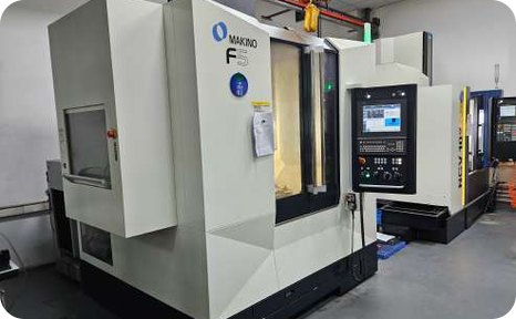
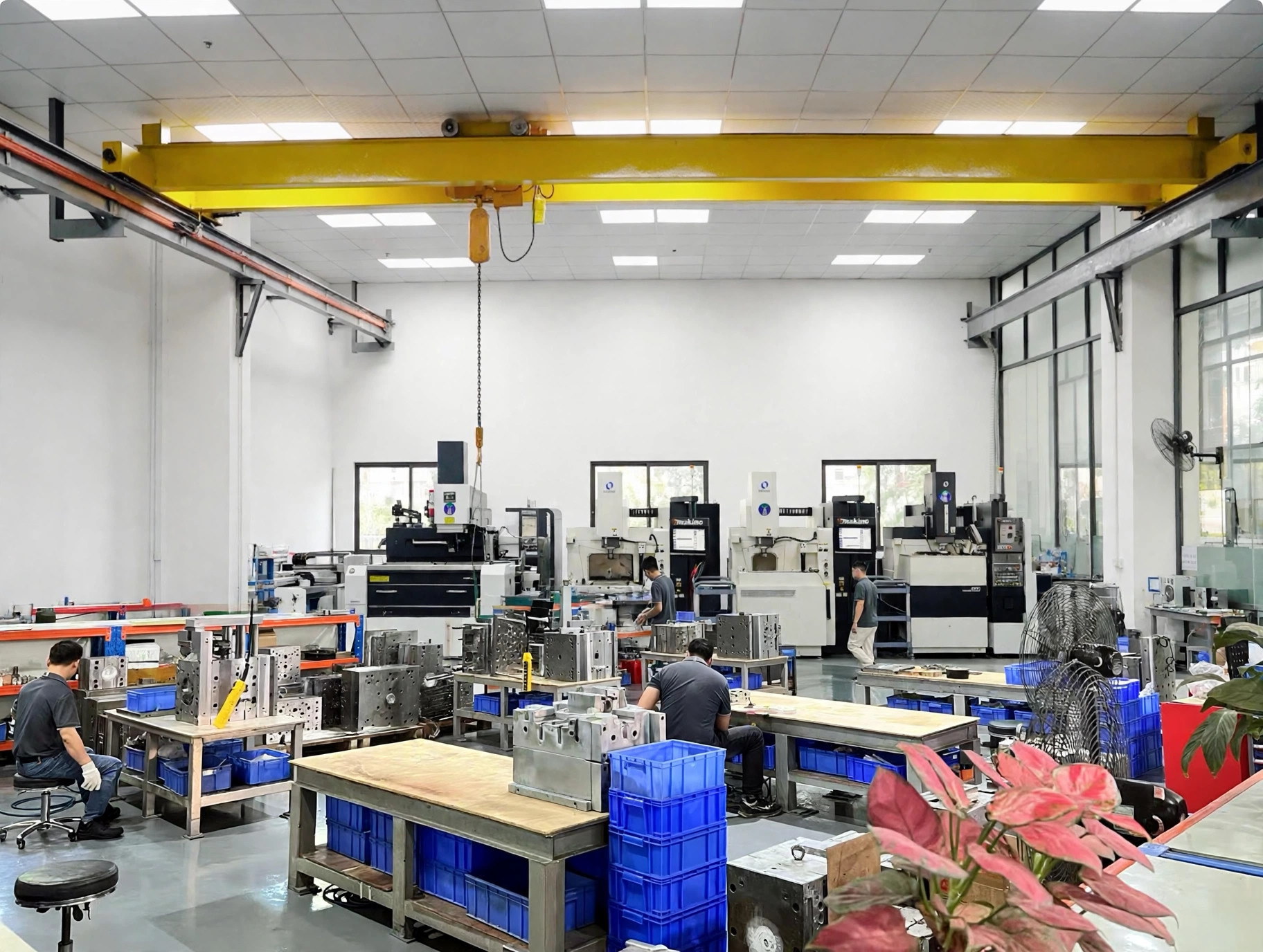
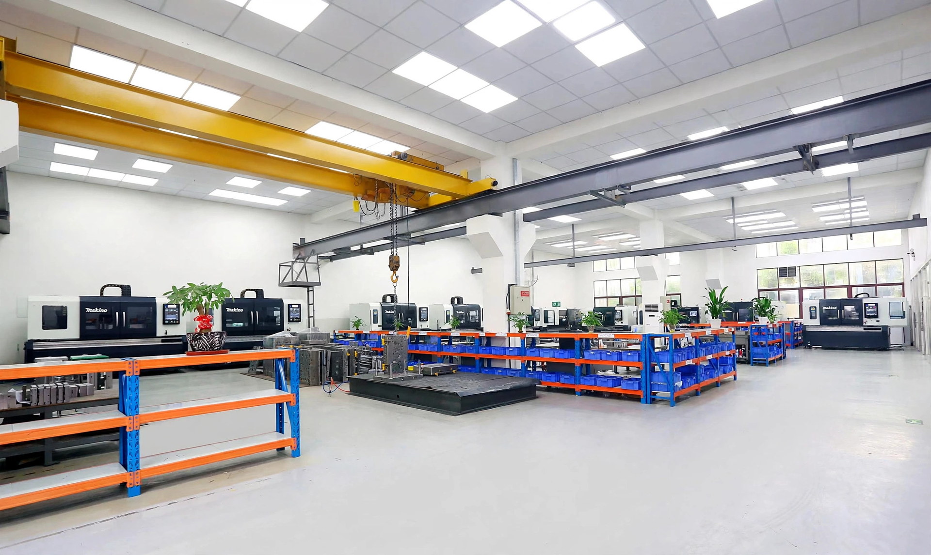
See the environment behind the tooling work
See the machining, fitting and dimensional inspection environment supporting WOKE Molds tooling projects.

Five phases with visible buyer dependencies
How requirements become a validation plan
These review scenarios connect a functional requirement to tooling decisions and the evidence needed for approval.
Internal cap with a defined start orientation
- Requirement
- Clean internal release plus a controlled relationship between thread start and an external datum.
- Design review
- Confirm lead and starts, create a datum chain, choose anti-rotation surfaces, coordinate core home and clearance, and protect the sealing face.
- Validation to define
- Conditioned-part dimensions, mating engagement, clocking method and sequence-state evidence.
Multi-cavity female connector with serviceable drive
- Requirement
- Consistent engagement across cavities with wear items accessible for maintenance.
- Design review
- Check cavity loads and thermal balance, transmission load distribution, replaceable guides/bearings and receiving-press handshake.
- Validation to define
- Cavity-correlated thread results, mating function, home/end checks and post-service verification.
Acceptance follows the drawing and the assembled requirement
Thread gauging is useful but not sufficient by itself. Measurement timing and conditioning matter for molded plastic, and sealing belongs to the whole joint.
| Requirement | Method to agree | Evidence |
|---|---|---|
| Thread geometry | Drawing-controlled plug/ring or custom profile/multi-start gauge; dimensional, optical or CMM checks where relevant | Defined inspection record after agreed conditioning |
| Mating function | Production-representative mating part; engagement, clocking and assembly-torque criteria | Functional result tied to part and revision |
| Seal requirement | Agreed joint test including mating faces, gasket, media, pressure and condition | Leak-test record when scoped; a thread gauge alone is not seal evidence |
| Mechanism sequence | Home/end feedback, interlocks, recovery and prevention of out-of-sequence eject/close | Trial checklist and issue/correction record |
| Released process | Material, settings, revision and controlled deviations | FAI, thread or mold-trial report as required by scope |
Design for Maintenance and Wear-Part Replacement
The wear chain can include rotating cores and sleeves, drive guides, gears or racks, bearings, seals, sensors and anti-rotation features. Access, lubrication policy and replaceable items are designed around the actual mechanism.
- Service accessReach wear items and sensors without disturbing unrelated alignments where practical.
- Released support setProvide the agreed spares/BOM, drawings, utilities and maintenance instructions.
- Post-service checkReconfirm home/end states, clearance, mating function and any affected dimensions.
- Evidence-led intervalsInspection and replacement intervals follow the actual mechanism, resin, loading and observed production wear.
Price the thread, mechanism and receiving cell together
Primary cost drivers include thread geometry and required revolutions, cavities, actuation and control, transmission, cooling, gauges, trial scope and spares. Current CAD and the mating drawing are the most useful first inputs.
Thread and cavity layout
Profile, starts, engagement, orientation and combined cavity load.
Drive and controls
Actuator, transmission, feedback, controller and press handshake.
Thermal and validation
Rotating-core cooling, resin behavior, gauges, mating tests and trials.
Lifecycle scope
Specified components, spares, documents, packing and support.
What to send, and what the package should define
Useful buyer inputs
- Part and thread
- 3D/2D files, standard or custom profile, starts, lead, hand, engagement, orientation and cosmetic zones.
- Material and mating system
- Exact grade/filler, mating part or drawing, assembly and seal criteria.
- Production plan
- Demand, cavities under consideration, receiving press and available utilities.
- Standards
- Tool standard, preferred drive/component vendors, gauges, records and shipping destination.
Package to confirm
- Tool and mechanism
- Cavity layout, drive source, transmission, cooling and specified components.
- Cell interfaces
- Controller, cables, hydraulic/power connections, fixtures, signals and integration responsibility.
- Trials and acceptance
- Representative material, mating parts, measurements, functional checks and approval route.
- Handover and support
- Released documents, scoped records, spares, preservation, packing and after-sales scope.
Typical mold lead time is 4–8 weeks, confirmed with the quotation. Actual timing depends on complexity, steel, mechanism components, finish, validation and customer approvals. EXW, FOB or DDP terms are agreed per quotation.
Request a Tooling ReviewPrepare the complete interface for the receiving plant
Handover can include mold and utility interfaces, controller documentation, released drawings, scoped inspection and process-setting records, agreed spares and maintenance information. Export tooling is rust protected, vacuum packed and secured in a wooden case for the quoted shipment route.
After delivery, remote technical support can coordinate issue analysis. Modification, spare, repair or on-site work is handled according to agreed scope and evidence from the receiving cell.

Practical details that change an unscrewing-mold RFQ
What if our files are incomplete?
Send the current model/drawing and intended mating function. We will identify the missing thread, material or press information that blocks a dependable quotation.
Do you need the mating part?
A physical mating part or controlled drawing is strongly useful for engagement, stop, clocking and joint-level test planning.
Can you mold custom, multi-start or tapered threads?
They require profile, lead, starts, runout, release and gauging review. Feasibility and acceptance are confirmed for the actual geometry.
Can the resin grade change after approval?
Review and revalidate grade, filler or supplier changes because shrinkage, friction, stiffness, cooling and mating behavior may change.
Should threads be gauged hot?
Inspection state must be defined. Molded-plastic dimensions are normally tied to an agreed conditioning and timing rather than an unspecified hot-part check.
Can cavity count be expanded later?
Sometimes, but cavity load, layout, drive capacity, cooling, controller and mold envelope should be evaluated before release; later expansion is not assumed.
What if the receiving press changes?
Recheck mounting, daylight, stroke, ejector, utilities, drive power, controller signals and recovery sequence before production transfer.
Do samples help with quotation?
Yes, especially a mating part and representative molded sample, but controlled drawings remain necessary for geometry and acceptance.
Is a parting witness acceptable?
That is a product decision. If witness lines are acceptable and geometry is accessible, a split route may be preferable to rotational release.
Can we specify the drive vendor or standard?
Yes. State preferred components, controller environment and plant standards so availability, integration and spares are included in the quotation.
How is maintenance supported?
The scoped handover can include BOM/spares, released drawings, lubrication and inspection guidance, plus remote issue analysis and quoted repair or modification work.
Is on-site support available?
Share the destination, access conditions, timing and required work so on-site arrangements can be assessed and included in the agreed support scope.
Review Your Threaded Part
Send the part CAD, thread or mating drawing, and requirements you have. Resin grade and receiving-press details help us define the next tooling review.