Injection molding workshop with production equipment

Finished molded-part manufacturing

Molding Processing

Custom molded parts from our own molding plant in Shenzhen. WOKE Molds connects material and tooling decisions with trials, production controls and repeat supply.

Service routes

Four routes to custom molded parts

The best route follows the part architecture, interface and supply plan—not a process label chosen in isolation.

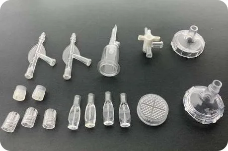
Assorted clear molded plastic components

Plastic Injection Molding

For housings, brackets, covers and functional components based on one principal molded resin system. The route is familiar, but gate position, shrinkage, local mass and cosmetic zoning still need deliberate control.

Explore plastic injection molding
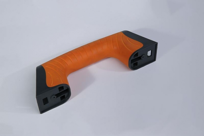
Molded handle with contrasting orange grip and black end regions

Two-Shot Injection Molding

For two colors or materials formed in a coordinated sequence. It can reduce separate handling and create integrated regions, but requires stable first-shot location, compatible tooling and a justified cell strategy.

Explore two-shot molding
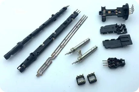
Black plastic components with visible metal contacts

Metal Insert Molding

For threads, contacts, terminals, bushings and load-transfer features retained in plastic. Insert location, support, cleanliness, plating and protected surfaces become central production controls.

Explore metal insert molding
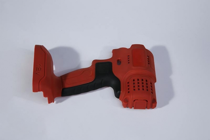
Red molded housing with a contrasting black grip region

Overmolding

For a second material molded onto or around a prepared substrate. The substrate may be transferred in a two-shot cell or produced and reloaded separately; interface condition determines what must be validated.

Explore overmolding

Route selector

Start with what the part needs to do

Select the feature that drives your part, then compare the route, inputs and interface decisions behind it.

A principal molded resin system

Likely route: plastic injection molding. Start with the exact grade or required performance, part geometry, annual demand and acceptance features. Compare an alternative only when another material, retained element or secondary operation performs a necessary function.

Review the base route

Two regions formed in sequence

Likely route: two-shot molding when coordinated transfer and volume justify the tooling/cell. A two-color hard/hard part may be two-shot without the soft-touch relationship often called overmolding. Conversely, two-shot equipment can produce an overmolded hard/soft relationship.

Review coordinated molding

Metal retained in molded plastic

Likely route: metal insert molding. Define alloy, plating, burr/cleanliness state, protected surfaces and the load path. Combining metal retention with an additional overmolded region is possible in principle, but needs project-specific tooling, sequence and validation review.

Review insert controls

A second material on a prepared substrate

Likely route: overmolding. The substrate source, age, moisture, contamination, surface treatment and locating method affect the interface. A material-family list is not a bonding guarantee; exact grades and retention design must be reviewed together.

Review interface decisions

Manufacturing responsibility

Compare the production routes

What the quotation and production plan must control for each route
Decision Injection molding Two-shot Metal insert Overmolding
Input stream Exact resin, color and additives Both grades plus sequence Resin and controlled metal inserts Second material and prepared substrates
Tool or cell dependency Tool matched to press and part Transfer, rotation, index or core-back concept Nests that locate, support and protect inserts Substrate source plus locating/shut-off method
Critical control Shrinkage, gate, cooling and ejection First-shot stability and second-shot boundary Insert position, movement and protected faces Surface state, retention and interface flash
Compare an alternative when A second function drives assembly or handling Volumes or variants do not justify coupled tooling Post-mold insertion or assembly better suits the load or service requirement Mechanical assembly avoids uncertain adhesion

Material function map

Choose materials for the real conditions

A resin name is only the first branch of the decision. Specify the exact grade when possible and connect it to heat, chemicals, load duration, moisture, flame requirement, appearance, regulatory context and expected conditioning.

Fillers, colorants, recycled content targets and other additives can change shrinkage, surface, weld behavior and interface performance. For two-material parts, compatibility depends on exact grades, temperature history, geometry and preparation—not simply whether two families appear on a chart.

General-purpose

PP / ABS
Useful starting families for many housings and consumer or industrial components; grade selection still follows stiffness, impact, chemical and finish needs.

Structural engineering

PC / PA / PBT / POM
Review moisture, creep, friction, dimensional stability, glass reinforcement and chemical exposure against the real duty cycle.

Flexible regions

TPE / TPU
Hardness alone is insufficient. Define feel, compression, wear, fluid exposure and how the interface will be retained or tested.

Higher-performance

PPS / PEEK / LCP / PPA
Use only after exact-grade, tool, processing, supply and commercial review; family-level properties do not establish part performance.

A dimension-critical housing

Start with the assembly datums and the dimensions that control fit. Confirm the resin grade, reinforcement, moisture or conditioning state and measurement method before freezing the tool shrinkage basis. A dimension measured immediately after molding may not represent the agreed service or inspection condition.

A grip or compressible sealing region

Specify whether the priority is touch, friction, abrasion, chemical exposure or compression. A matching Shore hardness does not establish equivalent grip, sealing or adhesion. Screen the named material pair, retention geometry and service environment, then validate the relevant function.

Supplier references such as Avient’s TPE selection guidance support grade screening; they do not replace a part-specific approval basis.

Design for molding

Resolve the design risks before tooling

Early RFQ clarification aligns scope and quotation assumptions. Formal DFM follows project kickoff, when the selected route, tool concept and acceptance plan can be reviewed together.

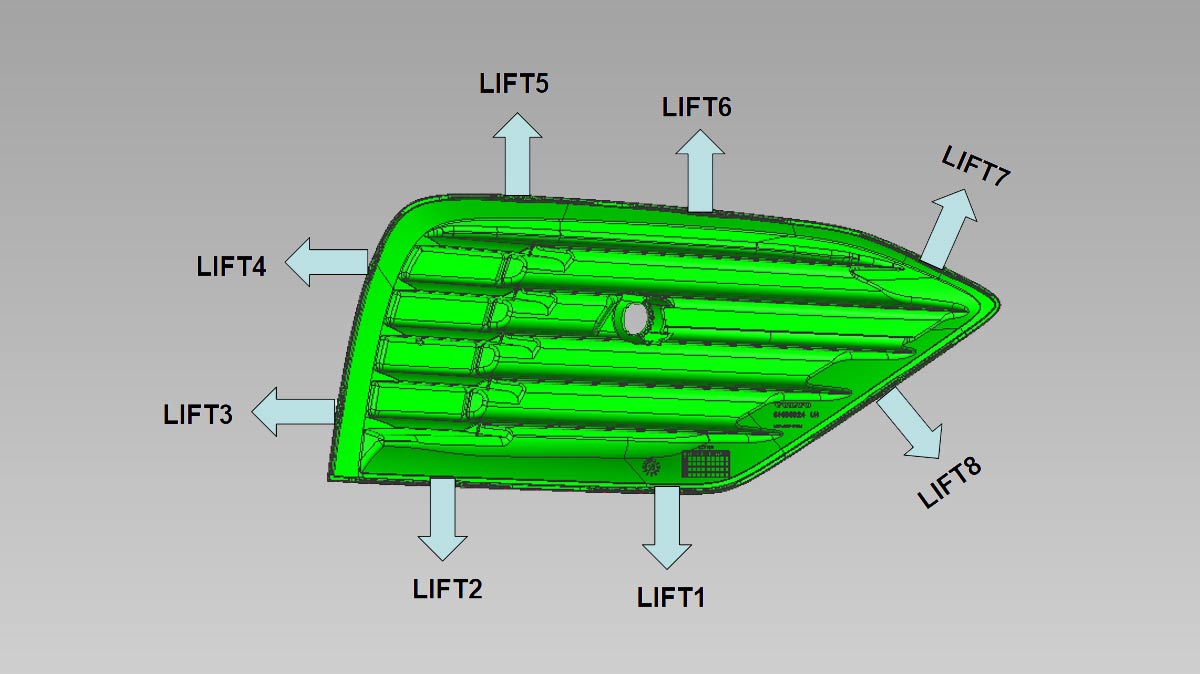
DFM reference showing a ribbed plastic part and labeled release directions
An example DFM reference showing how manufacturability observations can be communicated; project reviews are part-specific.

Mass and transitions

Review walls, ribs, bosses and thickness changes for sink, packing and cooling imbalance.

Release and appearance

Connect draft, texture, ejection, parting lines and gate evidence to named cosmetic zones.

Flow and stability

Consider weld locations, vents, cooling and shrink behavior against interfaces and datums.

Retained features

Resolve insert support, substrate shut-offs, undercuts, access and mechanical retention before the tool concept is fixed.

Enlarged example DFM analysis drawing

Project gates

From drawings to production approval

Project approval gates are not the same as the physical molding cycle. Each gate closes a different commercial or engineering uncertainty.

Define quotation assumptions

Available CAD or drawings, material intent, demand profile, destination and CTQs establish a comparable scope. Unknowns are recorded rather than hidden behind a headline price.

Kick off DFM and tooling decisions

The team reviews geometry, tool concept, cavity strategy, interface needs and responsibilities. Tool ownership, project documents and any tool-only handover are stated in the commercial scope.

Trial, correct and measure

Parts are evaluated in an agreed process and conditioning state. Dimensional, cosmetic, interface and functional evidence is reviewed; a sample is evidence for approval, not automatic approval of every production condition.

Approve recurring controls

The agreed production window, inspections, packing, trace links and change-review rules become the repeat-order baseline.

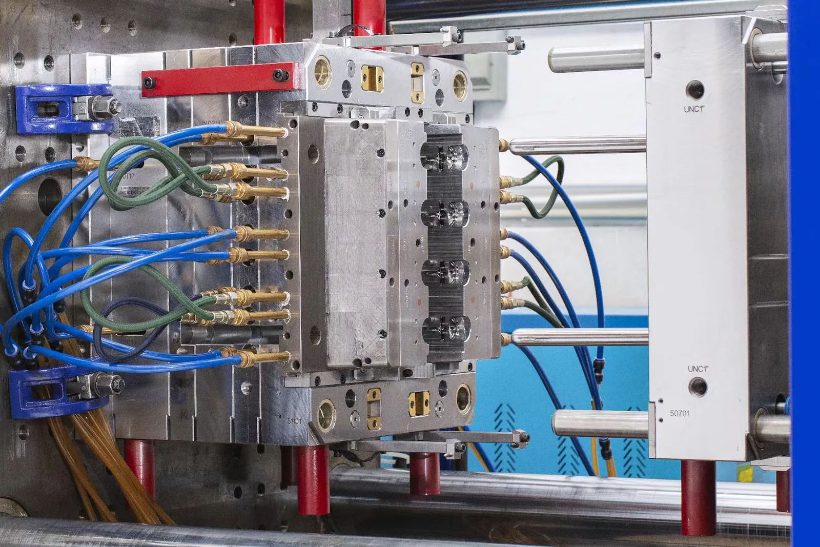
Injection molding press used for molded-part production
Production planning connects material identity and machine setup with inspection and release.

Production control

Keep the production run under control

  1. Material and incoming identity: confirm resin, additives, inserts or substrates and required preparation.
  2. Setup and first article: establish the tool, cell, loading method and initial acceptance evidence.
  3. Recorded molding window: control the approved setup while recognizing that inject, pack, cool and eject details vary by route.
  4. In-process and changeover checks: monitor the features that can drift and protect material or component identity between runs.
  5. Packing release: link accepted output to the defined lot, protection method and destination requirement.

Acceptance evidence

Define what an accepted part must prove

A useful quality plan names the characteristic, condition, method and record. It does not assume that every document or test applies to every molded part.

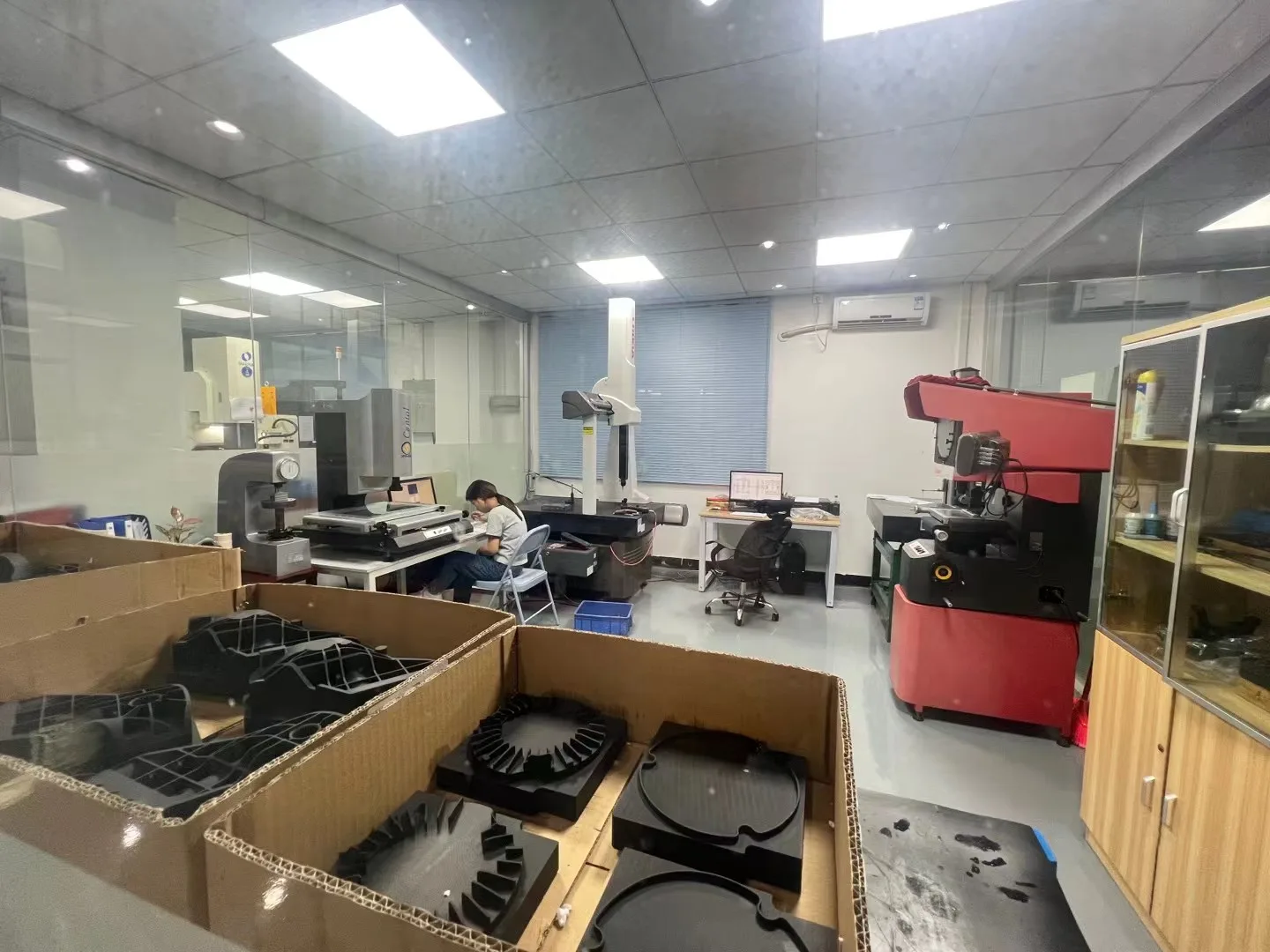
Dimensional inspection room with measuring equipment and molded components

Dimensions

Tie each critical characteristic to the drawing revision, datum system, fixture and conditioning state. Agree which dimensions need first-article, in-process or outgoing checks and how sample results will be judged.

Appearance

Identify visible faces and define lighting, viewing distance, texture/color references and permitted flash, gate vestige or witness marks. A cosmetic master and a dimensional report answer different questions.

Interfaces and function

Distinguish position, retention and finished function. An interface test needs a load direction, fixture, conditioning and limit; seal or electrical checks also need the relevant assembly and environmental conditions. Agree the method and scope before treating a result as acceptance.

Records

Select FAI, dimensional/CMM reports, supplier material evidence, inspection records, lot traceability or PPAP-related submissions to match the project. Specify the revision, sampling depth and required record package so documentation supports the acceptance decision.

A resin grade’s flame rating or supplier certificate does not by itself approve the geometry, wall thickness, assembly or finished product.

Make the approval transferable to the next order.

Record the approved part revision, material/source, reference samples and any accepted deviations. Link trial findings to corrections and confirm which checks must be repeated after a material, tooling, process or inspection change. First-piece approval, batch inspection and final product-function approval serve different purposes.

Risk review

Turn defects into a clear review plan

Symptoms can have multiple interacting causes. These review paths guide investigation; they are not one-setting fixes.

Sink or read-through near local mass

Review wall transitions, ribs, bosses, gate influence, packing and cooling. Validate with named visual zones and dimensional sections after consistent conditioning.

Warp or datum movement

Review shrinkage direction, reinforcement, geometry restraint, cooling and moisture conditioning. Compare parts using the agreed datum scheme, fixture and time after molding.

Short fill, weld weakness or trapped gas

Review flow path, venting, gate position, wall thickness and material condition. Evidence may include appearance sections and a relevant load or function test.

Flash at a parting line or shut-off

Review tool fit, support, pressure demand and substrate variation. Inspect the defined boundary and any interface that must remain clean or sealed.

Metal insert shifted or exposed

Review insert tolerances, burrs, nest support, loading, pressure forces and protected surfaces. Verify position, resin coverage and the specified pull, torque, electrical or assembly function.

Peeling or weak material interface

Review exact material pair, substrate age, moisture, contamination, temperature history, shut-off and retention geometry. Validate with a defined adhesion or functional method—not a family-name assumption.

Program economics

See what drives total part cost

One-time or launch investment

  • Tool architecture, cavities, gating and cooling
  • Insert nests, substrate fixtures or transfer features
  • Trials, corrections and agreed validation evidence

Recurring order cost

  • Resins, colors, inserts and prepared substrates
  • Cycle, loading, handling, yield and inspection
  • Packing, release records and delivery terms

Lifetime demand affects architecture. Expected total volume and batch size influence cavity strategy, automation and how much coupled equipment is sensible.

Variants affect flexibility. Color, material, insert or substrate variants can make changeover and inventory control more important than nominal cycle time.

Availability affects repeatability. Exact-grade and component sourcing should be reviewed before the baseline is approved. MOQ and schedule are confirmed from the actual project, not fixed here.

Compare quotations on the same basis

Accepted output
Clarify whether the price includes supplied inserts/substrates, setup allowances, inspection and the packing unit. Compare accepted finished parts, rather than an isolated machine cycle.
Batch and variant assumptions
Use the same order quantity, release pattern, resin/color variants and cavity plan. A yearly forecast does not mean every release can use the same setup or unit economics.
Tool and evidence scope
Separate tooling ownership, maintenance/storage arrangements, trial scope and one-time validation from routine production records. Confirm which items are included and which need a separate quotation.

Repeat supply

Keep repeat orders on the same basis

Repeatability depends on preserving the approved definition. Revision, resin grade, color, insert finish, substrate source, process route, cavity or packing changes should enter an agreed review—not an automatic substitution.

Define how incoming lots connect to production batches, which samples or records remain traceable, and how parts are stored and surface-protected. Order cadence and destination shape the packaging and logistics plan.

Protect the surfaces that do the work

Identify cosmetic faces, soft grips, sealing edges, threads and exposed contacts before choosing bags, separators or trays. Review nesting pressure, abrasion, deformation, dust and moisture against the part and transport route. A packaging sample can establish the pack-out basis when the risk justifies it.

Make the receiving check clear

Agree part number, revision, quantity and lot identification, along with mixed-lot rules, carton limits and any destination handling requirement. Keep the packing revision and order-release basis with the approved part definition so a repeat shipment can be checked against the same criteria.

Made in our own plants

Connect tooling, molding and delivery

15+ yearsTeam industry experience supporting mold and molded-part programs.

30–380T class41 presses from 30 to 380 tons in our Shenzhen plant, matched to the part size, material, tool and order.

One project pathMold development, molding, quality and delivery in-house, with one project contact.

Planning questions

Questions before a molding project

What if I do not know which molding route I need?

Share the part geometry, functions, material intent and demand. The route can be compared from the required interfaces, handling and validation rather than from a label.

Are you quoting a mold or finished molded parts?

This page covers finished-part programs, including the tooling. If your purchase is an export mold without recurring part supply, use the injection mold manufacturing service.

Are two-shot molding and overmolding mutually exclusive?

No. Overmolding describes a material molded onto a substrate; two-shot describes one coordinated way to produce two regions. Some overmolded parts are two-shot, while others use separately loaded substrates.

Can one project combine metal inserts and overmolding?

Potentially, but the loading sequence, tool architecture, protected surfaces and validation plan need specific review. It is not an automatic standard configuration.

Can I choose from a generic material list?

Families help start the discussion, but the exact grade, additives, color and service environment establish the real processing and performance requirements.

What can I send at the first inquiry?

Send available 3D CAD or 2D drawings and describe function, material intent, demand, destination and important acceptance features. Unknown items can be clarified during review.

Who owns the drawings, inserts or substrate specification?

Responsibilities depend on the project. The quotation identifies customer-supplied and WOKE-sourced inputs, approved specifications, revision control and incoming acceptance.

Does an approved trial part approve production automatically?

No. Approval should state the material, process/conditioning state, measurement basis and controls that the sample represents, plus any remaining corrections or production evidence.

How are tolerances confirmed?

They are reviewed against geometry, resin behavior, tool concept, conditioning, datum strategy and measurement method. Critical dimensions should be identified rather than applying one number universally.

Does a resin certificate certify the finished product?

No. Material evidence supports the specified grade or lot; finished-product approval can also depend on wall thickness, design, processing, assembly and required testing.

What determines MOQ, part cost and schedule?

Tooling, cavities, material availability, insert or substrate sourcing, cycle, loading, inspection, packing, demand profile and approval work all contribute. They are confirmed from the project scope.

What happens when a repeat order changes?

Drawing revisions, resin or color changes, new insert finishes, alternate substrate sources, cavity changes and packing revisions should be reviewed against the approved baseline.

Can you support packing and international delivery?

Yes, packing and EXW, FOB or DDP terms can be scoped. Protection, carton requirements, destination, freight, duties and importer responsibilities are defined for the order.

Can you start with incomplete files?

Yes. Available files can begin a feasibility conversation, with missing specifications recorded as open assumptions before tooling or production commitments.

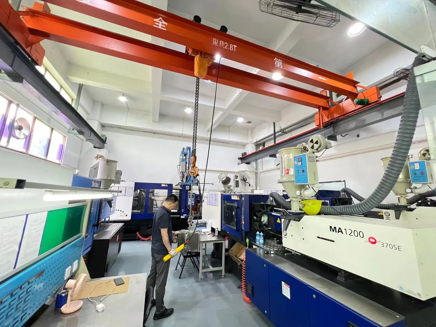
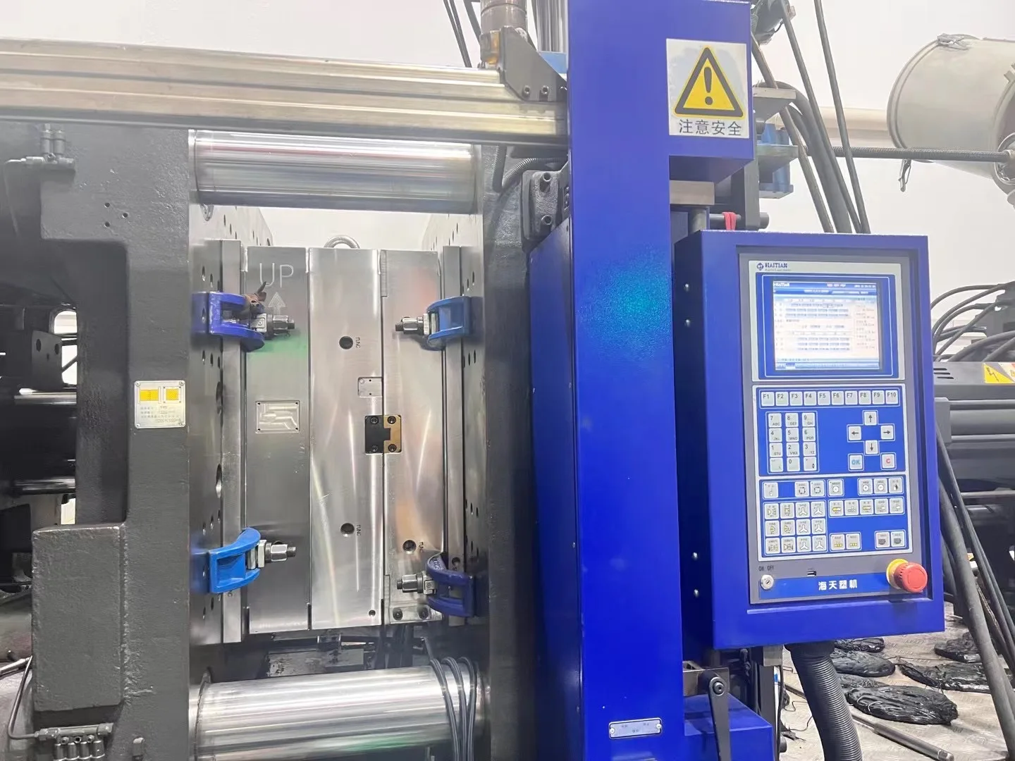
Injection molding machine and control panel in the workshop

Start with what you have

Discuss Your Molded Part

Share available drawings and the part’s function. Add material, demand and acceptance needs when known; open items can be clarified together.

Have 3D models or 2D drawings? Email your files to peter@wokemolds.com.

Please review our Privacy Policy before sending project details.