
Injection Molding Tool Design: Inputs, Layout and Gating
Injection molding tool design is the engineering work that turns a plastic part model into a mold that fills, cools, ejects and repeats reliably. It covers the parting line, cavity layout, gating, runners, cooling, venting, ejection, side actions, steel selection and the mold base. Good mold design decides part quality, cycle time and tool life long before the first steel is cut.
Most mold problems trace back to early design choices. For example, a small connector housing with a gate placed on the wrong side may weld at a latch, and no process setting will fully remove that line; moving the gate in the design review costs little, while moving it after hardening costs a new insert. In this guide, we explain injection molding tool design step by step: inputs, mold architecture, parting line, gating, cooling, ejection, undercuts, steel and standards, and how to review a design before release. For part-level rules, see our guide to basics of injection molding design.
Injection molding tool design defines how a mold makes a part: the number and layout of cavities, the parting line, gate and runner type, cooling circuits, vents, ejector system, slides or lifters for undercuts, mold steel and hardness, and the standard mold base and components. It starts from the part model, resin, annual volume, required tolerances and target press, and it is usually checked with DFM and, when the part needs it, Moldflow simulation. A design is ready to build when gating, cooling, ejection and steel choices are agreed and documented in a 3D mold design and a mold specification.
In short: design the mold around the part, the resin and the volume, then review it before cutting steel.
Key points:
- Inputs: part model, resin, volume, tolerances, press.
- Core decisions: cavities, parting line, gate, cooling, ejection.
- Release: DFM, simulation where needed, signed specification.
What Does Injection Molding Tool Design Include?
Injection molding tool design includes every system inside the mold that shapes, cools and releases the part.
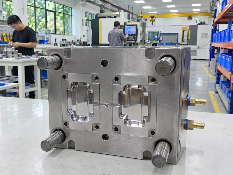
Main design systems:
- Cavity and core: form the part geometry and shrinkage allowance
- Parting line and shut-offs: where the mold opens and seals
- Feed system: sprue, runners and gates, cold or hot runner
- Cooling system: channels, baffles, bubblers and circuits
- Ejection system: ejector pins, sleeves, blades and stripper plates
- Side actions: slides, lifters and unscrewing cores for undercuts
- Mold base: plates, guide pins, bushings and locks
For example, a small two-cavity PC lens holder mold needs a polished cavity, a gate that avoids optical areas, balanced cooling and ejection on non-visible ribs. Our guide to injection mold components explains each part of the mold.
Key Takeaway: Above all, mold design is a system; each choice affects fill, cooling and ejection.
Which Inputs Are Needed Before Injection Molding Tool Design Starts?
Mold design needs clear inputs, or later changes will cost time and steel.
Required inputs:
- 3D part model and 2D drawing with tolerances
- Resin grade, including filler and flame rating
- Annual volume and expected mold life
- Cosmetic surfaces and texture or polish grade
- Target press size or the customer’s press data for export molds
- Standards for the mold base, components and hot runner brand
For example, a 500,000-shot PA66 GF30 clip needs hardened steel and wear-resistant gating, while a 20,000-shot ABS cover can use pre-hardened steel. Our injection molding quote RFQ checklist lists the data to send.
Key Takeaway: In other words, define volume, resin and critical features first; the mold follows them.
How Are Cavity Count and Mold Layout Chosen?
Cavity count and mold layout are chosen by volume, part size, tolerance and press capacity.
| Factor | Effect on layout |
|---|---|
| Annual volume | Higher volume favors more cavities |
| Tight tolerances | Fewer cavities make balance easier |
| Part size | Limits how many fit the press platen |
| Resin | Some resins need short, balanced flow |
| Budget | More cavities raise tool cost |
For example, a small precision gear may run in 4 cavities with a balanced runner, while a larger housing with tight flatness may stay single-cavity. Our guide to multi cavity injection molding explains cavity count decisions.
Key Takeaway: For this reason, choose cavities by part quality first and volume second.
How Do You Set the Parting Line and Draft?
The parting line and draft are set so the part releases cleanly and shut-offs seal well.
Design rules:
- Parting line on edges that are not cosmetic or functional
- Draft on all walls in the opening direction, more for textured faces
- Shut-off angles to avoid flash and wear
- Step parting lines only where the part requires them
For example, a textured cover needs extra draft on its side walls so the texture does not drag. Our guides to parting line injection molding and draft angle guidelines give details.
Key Takeaway: Overall, a clean parting line reduces flash, polishing and fitting time.
How Are Gates and Runners Designed?
Gates and runners are designed to fill the part evenly while keeping marks off important surfaces.
Main choices:
- Gate type: edge, submarine, pin-point, valve gate and others
- Gate location: thick section first, away from cosmetic and load areas
- Runner: cold runner for small, flexible volumes; hot runner for less waste and shorter cycles
- Balance: equal flow length to each cavity
For example, a submarine gate on a small part degates automatically during ejection and leaves a small mark on a side face. Our guide to injection molding gate types compares the options, and our guide to hot runner systems explains hot runner choices.
Key Takeaway: Equally, agree gate marks on the drawing before the design is released.
How Is Cooling Planned in Injection Molding Tool Design?
Cooling is designed to remove heat evenly so the part does not warp and the cycle stays short.
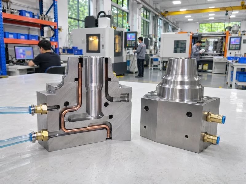
Cooling rules:
- Channels close to the cavity surface at even spacing
- Separate circuits for core and cavity
- Baffles or bubblers in deep cores
- Conformal cooling where straight drilling cannot reach
- Flow and temperature checked in simulation for critical parts
For example, a thin deep cup needs a bubbler in its core; without it, the core runs hot and the cup warps. Our guide to mold cooling channel design explains layouts, and Moldflow analysis shows how simulation checks them.
Key Takeaway: As a rule, cooling usually sets the cycle time, so design it early.
How Are Ejection, Venting and Undercuts Handled?
Ejection, venting and undercuts are handled with pins, vents and side actions placed around the part features.
- Ejectors on ribs, bosses and flat areas, balanced around the part
- Vents at the end of fill and where flow fronts meet
- Slides for external undercuts and side holes
- Lifters for internal snaps and clips
- Unscrewing or collapsible cores for internal threads
For example, a clip with an internal snap uses a lifter, and vents at the far end of the clip prevent burn marks. Our guides to injection mold venting, side action injection molding and injection molding lifters explain these features.
Key Takeaway: Furthermore, each undercut adds moving steel, so remove undercuts in part design when you can.
How Are Mold Steel and Standard Components Selected?
Mold steel and standard components are selected by resin, volume, finish and the customer’s maintenance needs.
| Mold need | Typical choice |
|---|---|
| Medium volume, general resin | P20 / 718H pre-hardened |
| High volume or filled resin | H13 / 1.2344 hardened |
| Mirror polish or corrosive resin | S136 / 1.2083 stainless |
| Mold base and components | HASCO, Meusburger, DME or MISUMI standard |
For example, a mold for a glass-filled PA66 part uses hardened inserts to resist wear at the gate. Our guide on how to choose mold steel gives more detail. Mold steel grades are also described in standards from ISO.
Key Takeaway: Consequently, match steel and component standards to the plant that will run and maintain the mold.
How Should an Injection Molding Tool Design Be Reviewed?
A mold design should be reviewed against the part, the process and the receiving press before release.
Review checklist:
- DFM report agreed: draft, wall thickness, gate, ejector marks
- Simulation results for fill, warpage and cooling where needed
- Press fit: mold size, tie-bar spacing, shot size and clamp force
- Steel and hardness per insert
- Maintenance: access to vents, gates and wear parts
- Sign-off of the 3D mold design and mold specification
For example, an export mold design should include the customer’s water connector type and locating ring size so it fits their press on arrival. Our guide to injection mold design review gives a full checklist, and our injection mold manufacturing team designs precision molds with Siemens NX and Moldflow where the project needs it.
Key Takeaway: Finally, release steel only after the design and specification are signed.
FAQ
- Q: What is injection molding tool design?
- It is the engineering of the mold’s cavities, gating, cooling, ejection, side actions, steel and mold base.
- Q: What information is needed for mold design?
- A 3D model, 2D drawing, resin, annual volume, cosmetic requirements and press data.
- Q: How long does mold design take?
- Simple molds take days; complex multi-cavity or 2K molds can take two weeks or more.
- Q: Is Moldflow always needed?
- No, it is used according to part complexity, tolerance and risk.
- Q: Which software is used for mold design?
- Common tools include Siemens NX, CATIA, Creo and SolidWorks with mold design modules.
Conclusion
Injection molding tool design turns a part model into a mold that fills, cools and ejects consistently. Start with clear inputs, choose cavities, gating, cooling, ejection and steel together, and review the design before cutting steel. To review your mold project, send your 3D model and 2D drawing to our engineers.