
Mold Cooling Channel Design: Rules, Testing and Handover
Mold cooling channel design decides how fast a molded part solidifies, how evenly it shrinks and how stable the cycle stays. Cooling usually takes the largest share of the cycle time, so channel layout, size and flow control directly affect part cost and quality. Good design on paper, however, is only half the job. The channels must also be tested, balanced and documented, so the mold cools the same way at the trial and years later in production.
Many cooling problems are found too late. For example, a mold may pass its trial with good parts, then warp parts in production because one circuit was connected in series with another at the customer’s press. Similarly, a slow leak found after shipping can stop production for days. In this guide, we explain mold cooling channel design together with flow balance records, water circuit pressure testing, multi-cavity circuit isolation and the cooling port map for handover. For cooling basics, see our guide to practical mold cooling.
Mold cooling channel design places channels close to and evenly around the cavity, typically at a distance of about 1–2 times the channel diameter from the surface and a pitch of about 3–5 diameters, sized for turbulent flow (Reynolds number above about 4,000–10,000). Each circuit should have a measured flow rate and a temperature rise of about 2–3 °C or less between inlet and outlet. Before shipping, every circuit should pass a pressure test, multi-cavity circuits should be checked for isolation and balance, and a labeled cooling port map should be handed over with the mold.
In short: design channels for even, turbulent cooling, then prove each circuit with flow, pressure and isolation tests and document it.
Key points:
- Layout: even distance and spacing around the cavity.
- Flow: turbulent flow and a small temperature rise per circuit.
- Records: pressure test, flow balance and a port map at handover.
What Are the Basic Rules of Mold Cooling Channel Design?
The basic rules of mold cooling channel design keep the cavity surface at an even temperature with enough heat removal.
| Rule (typical) | Guideline |
|---|---|
| Channel diameter | about 6–14 mm, by mold size |
| Distance to cavity surface | about 1–2 × diameter |
| Pitch between channels | about 3–5 × diameter |
| Flow regime | turbulent (Re above about 4,000–10,000) |
| Temperature rise per circuit | about 2–3 °C or less |
| Circuit length | short enough to keep temperature rise low |
Other good practice includes baffles or bubblers for deep cores, separate circuits for core and cavity, and cooling for slides and lifters where they form large areas. For example, a deep cup-shaped part needs bubblers inside the core, because straight drilled lines cannot reach the core tip. Our guide to conformal cooling explains when 3D-printed channels help.
Key Takeaway: In mold cooling channel design, cool the core as carefully as the cavity. Hot cores cause most warpage.
How Is Mold Cooling Channel Design Checked at Mold Trials?
Flow balance is recorded at mold trials by measuring the flow rate and temperature rise of every circuit and writing them into the trial report.
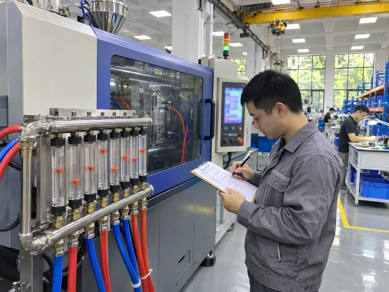
A cooling record includes:
- Circuit number matching the port map
- Flow rate, in L/min, for each circuit
- Inlet and outlet temperature and the difference
- Mold surface temperature at several points
- Water temperature and pressure from the temperature controller
For example, if circuit 3 shows half the flow of the others, a partly blocked channel or a wrong connection is likely. Correcting it before approval avoids a hot spot in production. Our guide to injection mold cooling time calculation explains how cooling links to cycle time.
Key Takeaway: Ask for flow and temperature per circuit in the trial report. It becomes the baseline for production.
How Should a Water Circuit Pressure Test Be Accepted?
A water circuit pressure test should be accepted when every circuit holds a specified pressure for a specified time without loss or visible leaks.
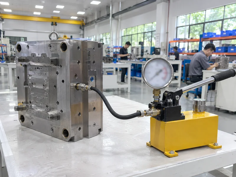
Typical acceptance points:
- Test medium: water or air, as agreed
- Test pressure: above normal working pressure, for example about 1.5 times
- Hold time: for example 10–30 minutes
- Criterion: no pressure drop beyond an agreed limit and no visible leakage
- Record: circuit number, pressure, time and result
For example, a slow leak at an O-ring between plates may only appear under pressure after the mold warms up. Testing both cold and at operating temperature catches it. Hydraulic and pressure test principles are described by standards bodies such as ISO.
Key Takeaway: Good mold cooling channel design still needs testing. Agree pressure, time and pass criteria in writing. “No leak” is not a measurable criterion on its own.
How Do You Test Cooling Circuit Isolation in a Multi-Cavity Mold?
You test cooling circuit isolation in a multi-cavity mold by checking that each circuit is separate and that water entering one circuit leaves only from its own outlet.
Test methods:
- Isolation test: pressurize one circuit and check that no flow appears at other outlets.
- Flow check: measure flow per circuit with all circuits connected.
- Balance check: compare flow and temperature rise between cavities.
- Cross-drilling check: confirm there are no unintended intersections.
For example, an accidental breakthrough between two drilled lines can mix two circuits. As a result, one cavity runs hotter, and part weights differ. An isolation test finds it before shipping. Our guide to multi-cavity injection molding explains why cavity balance depends on cooling.
Key Takeaway: In multi-cavity molds, test each circuit alone. Mixed circuits create cavity-to-cavity differences.
What Should a Cooling Port Map for Handover Include?
A cooling port map for handover should show every water port, its circuit, its direction and how it should be connected.
A complete port map includes:
- Mold views with every port marked
- Circuit numbers and in/out labels
- Thread size of each port
- Connection plan, including which circuits may be joined
- Recommended flow and temperature from the trial
- Labels on the mold that match the map
For example, a mold shipped with clear “IN 1 / OUT 1” stamps and a matching map is connected correctly the first time at the customer’s press. Without it, circuits are often connected in series, which raises the temperature rise and changes part dimensions. Every export mold we ship is trialed and inspected before packing.
Key Takeaway: Ask for a labeled port map and matching stamps on the mold. It protects the trial results.
How Does Mold Cooling Channel Design Stay Effective Over the Mold’s Life?
You keep cooling performance over the mold’s life by keeping water clean, checking flow regularly and cleaning channels when flow drops.
Practical steps:
- Water quality: treated or filtered water reduces scale and rust.
- Flow checks: compare flow with the trial record at set intervals.
- Cleaning: descale channels when flow drops noticeably.
- Storage: blow out and dry channels before storing the mold.
- Seals: replace O-rings during major maintenance.
For example, a mold that slowly develops longer cycles over a year may have scaled channels. Cleaning restores the flow and the cycle. Our guide to mold maintenance covers more checks.
Key Takeaway: A trial flow record makes later cooling problems easy to spot.
FAQ
- Q: How far should cooling channels be from the cavity?
- Typically about 1–2 times the channel diameter from the cavity surface.
- Q: What temperature rise is acceptable in a cooling circuit?
- Usually about 2–3 °C or less between inlet and outlet.
- Q: Why is turbulent flow important?
- Turbulent flow removes heat much more effectively than laminar flow.
- Q: How is a mold cooling circuit pressure tested?
- Each circuit is pressurized above working pressure for a set time and checked for pressure loss and leaks.
- Q: What is a cooling port map?
- A document showing every water port, its circuit and direction, and how to connect it.
Conclusion
Mold cooling channel design sets cycle time and part quality, but only tested and documented circuits keep that performance in production. Design for even, turbulent cooling, record flow balance, pressure test and isolate circuits, and hand over a clear port map. To review cooling for your mold, send your 3D model and 2D drawing to our engineers.
For production support, explore our injection mold manufacturing service. You can also share your drawing for an engineering review.