
Injection Mold Cooling Time Calculation Formula: How to Beat It
The injection mold cooling time calculation formula for a flat wall is t = s² / (π² · α) · ln[(8 / π²) · (Tm − Tw) / (Te − Tw)], where s is wall thickness, α is the plastic’s thermal diffusivity, Tm is melt temperature, Tw is mold temperature and Te is the ejection temperature. Because thickness is squared, doubling the wall roughly quadruples the cooling time.
Cooling is usually the largest part of the molding cycle. Therefore, a quick estimate helps buyers and engineers compare part designs, cavity counts and quotes before a full simulation. For example, trimming a 3 mm wall to 2.5 mm can save about 30% of the cooling time, which can mean thousands of extra parts per week. In this guide, we explain the injection mold cooling time calculation formula, show a worked example and explain where the estimate stops being reliable. For the mold side of the topic, see our guide to practical mold cooling.
The standard injection mold cooling time calculation formula for a plate-shaped wall is t = s² / (π² · α) · ln[(8 / π²) · (Tm − Tw) / (Te − Tw)]. It estimates how long the thickest wall needs to cool from melt temperature to a safe ejection temperature at a given mold temperature. It is a first estimate: real cycle times also depend on cooling channel layout, steel, part geometry and process settings, so complex parts are better checked with mold flow simulation.
In short: wall thickness dominates cooling time, so the formula is most useful for comparing designs early.
Key points:
- Thickness squared: cooling time grows with the square of the thickest wall.
- Material and temperatures: diffusivity, melt, mold and ejection temperatures set the rest.
- Limits: the formula assumes ideal cooling, so real molds usually need more time.
What Is the Injection Mold Cooling Time Calculation Formula?
The injection mold cooling time calculation formula estimates the time needed for heat to leave the center of a molded wall through both faces into the mold. For a flat plate cooled from both sides, the common form is:
t = s² / (π² · α) · ln[(8 / π²) · (Tm − Tw) / (Te − Tw)]
For round sections, such as a rod or a thick boss, a cylinder form is used instead:
t = R² / (5.78 · α) · ln[0.692 · (Tm − Tw) / (Te − Tw)], where R is the radius.
Both forms come from transient heat conduction theory. However, both assume uniform mold temperature, perfect contact between plastic and steel and constant material properties. As a result, they give a lower-bound estimate for a well-cooled mold.
Key Takeaway: Use the plate form for walls and the cylinder form for thick round features. Apply it to the thickest section, because that section controls the cycle.
What Does Each Variable in the Injection Mold Cooling Time Calculation Formula Mean?
Each variable in the injection mold cooling time calculation formula represents a physical property or process setting. Getting the units right matters more than the math.
- s – wall thickness (mm): the thickest wall that controls ejection, not the nominal wall.
- α – thermal diffusivity (mm²/s): how fast heat moves through the plastic; it equals conductivity divided by density times specific heat.
- Tm – melt temperature (°C): the plastic temperature entering the cavity.
- Tw – mold temperature (°C): the average cavity surface temperature.
- Te – ejection temperature (°C): the temperature at which the part is rigid enough to eject without distortion.
Thermal diffusivity is measured with standard methods, such as the laser flash method published by ASTM International. In practice, buyers rarely have exact values. Therefore, typical datasheet values are used for estimates.
Key Takeaway: Use mm and seconds consistently. With s in mm and α in mm²/s, the result is in seconds.
How Do You Calculate Injection Mold Cooling Time Step by Step?
You calculate injection mold cooling time by inserting the thickest wall, the material’s diffusivity and the three temperatures into the formula. A worked example for an ABS part:
- s = 2.0 mm
- α ≈ 0.08 mm²/s (typical ABS estimate)
- Tm = 240 °C, Tw = 60 °C, Te = 90 °C
Step 1: temperature ratio = (240 − 60) / (90 − 60) = 180 / 30 = 6.0
Step 2: multiply by 8 / π² ≈ 0.811, giving about 4.86
Step 3: natural log of 4.86 ≈ 1.58
Step 4: s² / (π² · α) = 4.0 / (9.87 × 0.08) ≈ 5.07 s
Step 5: cooling time ≈ 5.07 × 1.58 ≈ 8.0 s
This is the cooling portion only. Injection, packing, mold opening, ejection and closing add to the total cycle. Our guide to estimating molding cycle time covers the full cycle.
Key Takeaway: Calculate with the thickest wall and typical values, then add the other cycle steps. The result is a comparison tool, not a promise.
How Does Wall Thickness Change Injection Mold Cooling Time?
Wall thickness changes injection mold cooling time more than any other variable, because the formula squares it. Using the same ABS values as above:
| Thickest wall | Estimated cooling time | Change vs 2.0 mm |
|---|---|---|
| 1.5 mm | about 4.5 s | about −44% |
| 2.0 mm | about 8.0 s | baseline |
| 2.5 mm | about 12.5 s | about +56% |
| 3.0 mm | about 18.0 s | about +125% |
| 4.0 mm | about 32.0 s | about +300% |
The business effect is direct. For example, a 4-cavity mold running 2,000 hours a year produces roughly twice as many parts at 2.0 mm walls as at 3.0 mm walls, if cooling dominates the cycle.
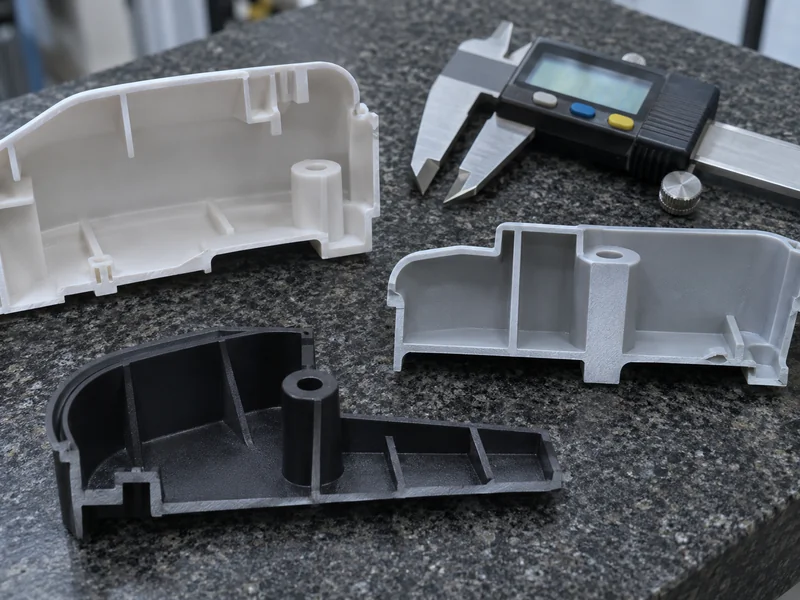
Thick bosses and rib intersections also count. A single thick boss can control the whole cycle, even when the rest of the part is thin. Therefore, coring out thick areas is one of the most effective cost reductions.
Key Takeaway: Find the thickest section in the part, not the nominal wall. Reducing that one section often saves more than any process change.
Which Material Values Should You Use in the Formula?
You should use the resin supplier’s data where available, and typical values for early estimates. The table below shows typical ranges for estimates only.
| Material | Typical α (mm²/s) | Typical melt (°C) | Typical mold (°C) | Typical ejection (°C) |
|---|---|---|---|---|
| PP | about 0.07–0.10 | 200–250 | 20–60 | 90–100 |
| ABS | about 0.08–0.10 | 220–260 | 50–80 | 85–95 |
| PC | about 0.10–0.12 | 280–310 | 80–110 | 125–135 |
| PA66 | about 0.09–0.12 | 270–300 | 70–90 | 140–160 |
| POM | about 0.08–0.10 | 190–220 | 80–100 | 140–150 |
These ranges vary by grade, filler and supplier. Glass-filled grades usually conduct heat faster, while flame-retardant grades can differ. Therefore, final cycle estimates should use the actual grade data.
Key Takeaway: Treat the table as a starting point. When the cycle time matters for a quote, ask for grade-specific values.
How Accurate Is the Injection Mold Cooling Time Calculation Formula?
The injection mold cooling time calculation formula is usually accurate enough to compare designs, but it often underestimates real cycles. Real molds cool less evenly than the formula assumes.
Common reasons real cooling takes longer:
- Cooling channels sit too far from the cavity or are unevenly spaced.
- Cores, slides and thin steel areas run hotter than the average mold temperature.
- Hot spots form at rib intersections and bosses.
- Water flow is too low to be turbulent, so heat removal drops.
For complex parts, mold flow analysis shows cooling time, hot spots and warpage before steel is cut. At WOKE Molds, Moldflow is applied according to project complexity and customer requirements, not on every project.
Key Takeaway: Use the formula for early comparisons and simulation for decisions that commit steel. When the two disagree, trust the simulation.
How Do Mold Design Choices Shorten Cooling Time?
Mold design choices shorten cooling time by moving heat out of the hottest areas faster and more evenly. The part design sets the minimum; the mold decides how close you get to it.
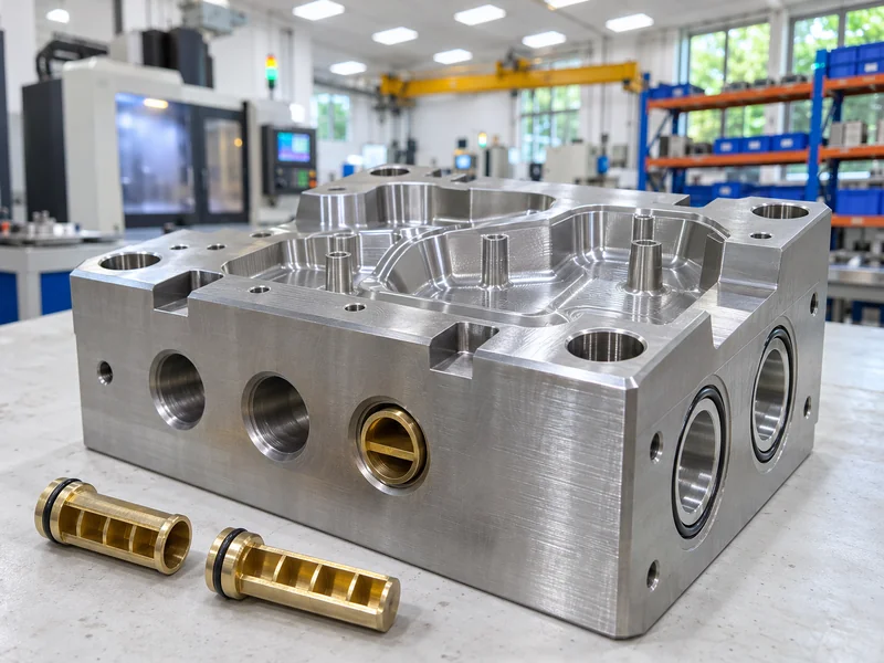
- Channel layout: keep channels at a consistent distance from the cavity surface.
- Baffles and bubblers: cool deep cores that cannot hold straight channels.
- High-conductivity inserts: use copper alloys in hot cores where wear allows.
- Conformal cooling: follow complex shapes with 3D-printed channels when the cost is justified.
- Separate circuits: balance cavity and core temperatures to reduce warpage.
For example, a tall core with only a straight channel at its base often runs much hotter than the cavity. A bubbler or a copper-alloy insert can cut seconds from the cycle. Our article on conformal cooling explains when 3D-printed channels pay back.
Key Takeaway: Cool the hottest steel first. Cores, bosses and deep ribs usually decide the real cycle.
What Cooling Time Mistakes Increase Part Cost?
Cooling time mistakes increase part cost by stretching the cycle or causing warpage and scrap. The most common mistakes are design choices made before anyone calculates cooling.
- Designing thick walls “for strength” instead of using ribs
- Leaving solid bosses instead of coring them
- Using one cooling circuit for both mold halves
- Setting mold temperature by habit rather than by material
- Ejecting too early to save time, which causes distortion
As a result, a part designed without a cooling estimate can cost far more per piece than necessary for its whole life.
Key Takeaway: Estimate cooling time during part design, not after the mold is built. It is the cheapest time to save seconds.
How Should Buyers Use Cooling Time in an RFQ?
Buyers should use cooling time to compare designs and to understand why quotes differ. A supplier quoting a longer cycle may be assuming a thicker section or a more conservative ejection temperature.
When requesting a quote, include:
- 3D model and 2D drawing, with critical walls and bosses visible
- Material grade, including any fillers
- Annual volume, so the supplier can size cavities
- Cosmetic and flatness requirements, which affect ejection temperature
We review wall thickness and cooling as part of mold design for custom injection molds.
Key Takeaway: Ask suppliers to state their assumed cycle time and thickest wall. It makes quotes comparable.
FAQ
- Q: What is the formula for injection mold cooling time?
- For a flat wall, t = s² / (π² · α) · ln[(8 / π²) · (Tm − Tw) / (Te − Tw)], with s as wall thickness and α as thermal diffusivity.
- Q: Why does wall thickness matter so much?
- Cooling time grows with the square of wall thickness, so doubling the wall roughly quadruples cooling time.
- Q: Is the cooling time formula accurate?
- It is good for comparing designs. Real molds usually need more time because cooling is never perfectly even.
- Q: What is a typical cooling time for a 2 mm ABS part?
- Using typical values, about 8 seconds of cooling, before injection, packing and mold movement are added.
- Q: How can I reduce cooling time?
- Reduce the thickest wall, core out bosses, improve cooling channel layout, and use baffles, copper-alloy inserts or conformal cooling where justified.
Conclusion
The injection mold cooling time calculation formula gives a fast, useful estimate driven mainly by the thickest wall. Use the injection mold cooling time calculation formula early to compare designs, then confirm with simulation for complex parts. To review cycle time and cooling for your part, send your 3D model and 2D drawing to our engineers.