
Parting Line Injection Molding: How to Pick the Best Spot
In parting line injection molding, the parting line is the line on a molded part where the two mold halves meet. The mold opens there to release the part. Therefore, it controls draft direction, flash risk, cosmetic surfaces and mold complexity. A well-placed parting line is nearly invisible; a poor one creates steps, flash and extra mold cost.
The parting line is decided early, often before the buyer sees the mold design. For example, a round handle split along its centerline needs no slides but shows a line on both sides. Moving the split to an edge hides the line but may need a slide. In this guide, we explain how parting line placement affects appearance, flash risk and tool access, and how air ejection helps deep parts release from the mold. For the wider design picture, see our injection molding design basics.
In parting line injection molding, the parting line is the boundary on the part where the cavity and core halves of the mold meet. It is usually placed at the largest outline of the part in the mold opening direction, away from cosmetic and sealing surfaces. Its position determines draft direction, undercuts and slides, venting, flash risk and witness lines, so it should be agreed with the toolmaker during design for manufacturing.
In short: put the parting line at the part’s widest outline, on a non-cosmetic edge, and keep it as flat as possible.
Key points:
- Placement: at the largest silhouette, in the mold opening direction.
- Appearance: away from cosmetic, sealing and grip surfaces.
- Cost: flat parting lines are cheaper and seal better than stepped ones.
What Is a Parting Line in Injection Molding?
In parting line injection molding terms, the parting line is the visible boundary where the cavity and core halves close together. When the mold opens, the part separates along this line.
Every molded part has at least one parting line. Parts with slides or lifters also have extra lines where those components meet the main mold.
The parting line usually shows as:
- A fine line on the part surface
- A small step, if the mold halves are slightly mismatched
- Thin flash, if plastic escapes between the mold halves
Key Takeaway: In parting line injection molding, you cannot remove the parting line, but you can choose where it goes and how visible it is.
How Does Parting Line Placement Affect Part Appearance?
In parting line injection molding, placement affects part appearance because the line, any mismatch and any flash appear exactly where the mold halves meet. Therefore, the line should sit where nobody looks or touches.
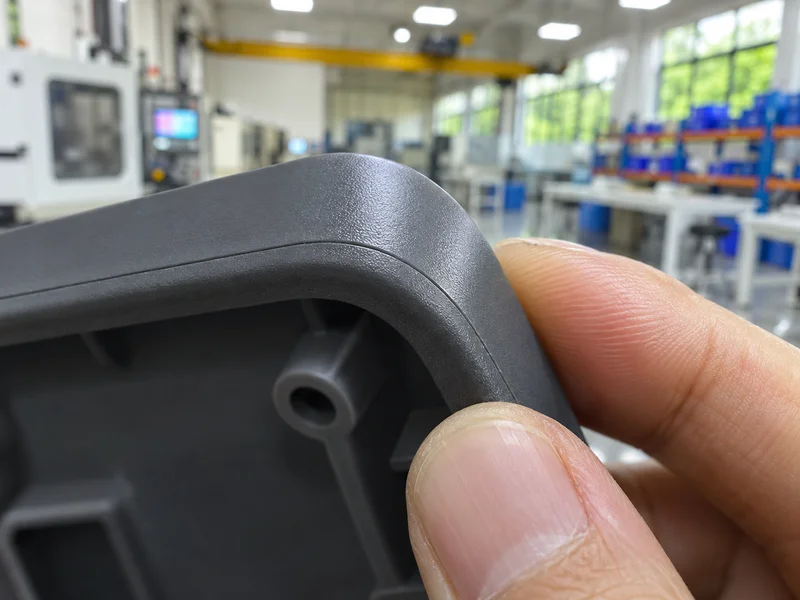
Good placement choices:
- On an edge or corner, where a line looks like a design feature
- On the back or inside, away from the user’s view
- On a step or groove, which hides small mismatch
- Away from grips, where flash would be felt
For example, a consumer housing often places the parting line on the outer edge of the rim, where a small radius or step hides it. Our guide to injection molding surface finishes explains how texture can also help hide witness lines.
Key Takeaway: Mark cosmetic surfaces on the drawing before mold design starts. The toolmaker places the parting line around them.
How Does Parting Line Injection Molding Affect Flash Risk?
Parting line injection molding affects flash risk because the parting line is the largest sealing surface in the mold. Any gap, wear or low clamping force lets plastic escape there.
Main causes of parting line flash:
- Complex 3D parting surfaces that are hard to fit perfectly
- Low clamping force for the projected area
- Worn or damaged parting surfaces
- Low-viscosity resins, such as PA and PP
- Excessive injection or packing pressure
- Vents that are too deep
Vents are often cut into the parting line, because it is the natural exit for air. They must be deep enough for air but shallow enough to stop plastic. Our guide to injection mold venting gives typical depths by resin.
Key Takeaway: A simple, flat parting line seals better and flashes less. Every step and curve adds flash risk.
What Is the Difference Between Flat and Stepped Parting Lines?
In parting line injection molding, the difference between flat and stepped parting lines is the shape of the surface where the mold halves meet. Flat lines lie in one plane; stepped or contoured lines follow the part shape.
| Parting line type | Description | Cost | Flash risk | Typical parts |
|---|---|---|---|---|
| Flat | One plane | Lowest | Lowest | Simple boxes, lids, plates |
| Stepped | Several flat levels | Medium | Medium | Housings with raised areas |
| Contoured (3D) | Follows a curved surface | Highest | Highest | Handles, ergonomic shapes |
| Angled | Inclined to the opening direction | Medium | Medium | Parts with angled edges |
Stepped and contoured lines need shut-off angles, so the mold halves do not rub and wear. Common practice uses shut-off angles of several degrees on vertical shut-off faces.
Key Takeaway: Ask whether a small design change could make the parting line flat. It often saves mold cost and reduces flash for the whole tool life.
How Does Parting Line Injection Molding Affect Draft, Undercuts and Slides?
Parting line injection molding decisions affect draft, undercuts and slides because the parting line defines the mold opening direction. Every surface must release in that direction, or the mold needs extra moving parts.
- Draft: walls draft away from the parting line on both halves.
- Undercuts: features that block opening need slides, lifters or redesign.
- Slides: add extra parting lines and cost, but allow side features.
- Core pins: holes in the opening direction are simple; side holes need slides.
For example, a side clip on a housing becomes an undercut if the parting line runs across the top. Moving the parting line, or redesigning the clip with a pass-through core, can remove the slide. Our guides to draft angles and undercuts cover these choices in detail.
Key Takeaway: Decide the parting line and the opening direction together. Undercuts and draft follow from that one choice.
How Should Drawings Control the Parting Line?
For parting line injection molding, drawings should show where the line may go. They should also state the allowed mismatch and flash. Without these notes, the supplier decides.
Useful drawing notes include:
- Location: the allowed parting line area, or “parting line per supplier, not on A-surface”
- Mismatch: the maximum step between mold halves
- Flash: the maximum flash allowed, or “no flash on sealing surfaces”
- Witness lines: acceptable or not on cosmetic faces
- Draft: direction and minimum angle relative to the parting line
General plastics tolerance standards, such as those published by ISO, help define tolerance classes for molded dimensions, including features that cross the parting line. Our guide to injection molding tolerances explains why dimensions across the parting line need more tolerance.
Key Takeaway: Dimensions across the parting line vary more than those within one mold half. Tolerance them accordingly.
How Does Air Ejection Help Parts Release From the Mold?
Air ejection helps parts release from the mold by blowing air between the part and the core to break the vacuum. Deep, thin-walled parts, such as cups, buckets and lids, often hold onto the core by suction rather than friction.
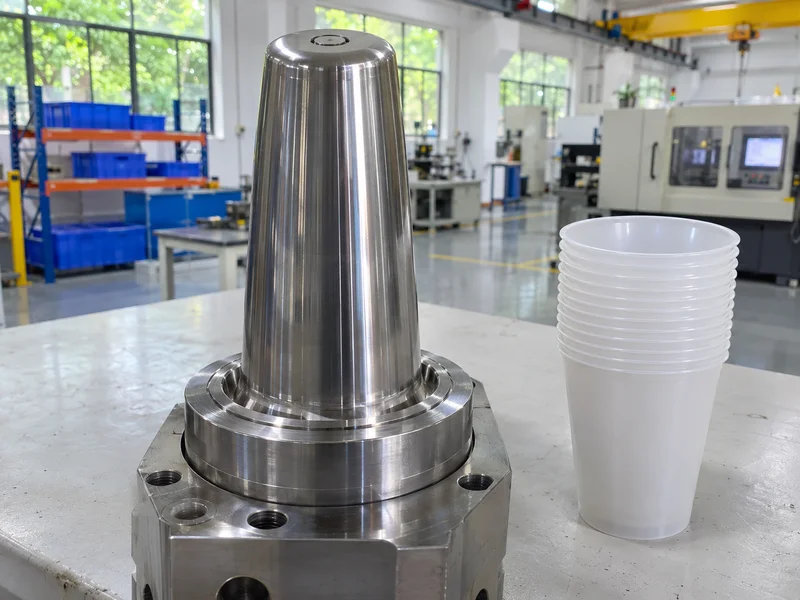
How injection mold air ejection works:
- The part cools on the core.
- A small valve, usually a spring-loaded poppet in the core, opens.
- Compressed air enters between the part and the core.
- The vacuum breaks and the part lifts off, often helped by a stripper ring.
Benefits of air ejection:
- Removes vacuum without pushing on thin walls
- Reduces or avoids ejector pin marks on visible faces
- Supports fast cycles on thin-wall packaging parts
However, air valves need clean, dry air and regular maintenance. For other ways to reduce marks, see our guide to ejector pin marks.
Key Takeaway: For deep cups and lids, combine air ejection with a stripper ring. It releases the part cleanly with almost no face marks.
How Do You Choose the Right Parting Line Early?
In parting line injection molding, you choose the right parting line early by reviewing the part with the toolmaker before the design is frozen. A short DFM review costs little and prevents expensive mold changes.
A practical review checks:
- Opening direction and the largest silhouette
- Cosmetic and sealing surfaces to protect
- Undercuts that a different parting line could remove
- Gate and vent positions relative to the parting line
- Ejection method, including air ejection for deep parts
- Flash and mismatch limits for the drawing
Our engineering and DFM review covers parting line, draft, gates and ejection as part of injection mold manufacturing.
Key Takeaway: Agree the parting line injection molding plan before the 3D design is final. It is the one mold decision that affects almost every other.
FAQ
- Q: What is a parting line in injection molding?
- It is the line on a molded part where the two mold halves meet and separate when the mold opens.
- Q: Can you avoid a parting line?
- No, but you can place it on an edge, step or hidden surface where it is almost invisible.
- Q: Why does flash form at the parting line?
- Flash forms when plastic escapes through a gap between mold halves, caused by wear, low clamp force, high pressure or complex parting surfaces.
- Q: What is a stepped parting line?
- It is a parting line on several levels, used when the part shape cannot be split on one flat plane.
- Q: What is air ejection in injection molding?
- It uses compressed air through a valve in the core to break the vacuum and release deep, thin parts such as cups and lids.
Conclusion
Parting line injection molding decisions control appearance, flash, draft, slides and mold cost. Place the line at the widest outline on a non-cosmetic edge, keep it flat where possible, and use air ejection for deep parts. To review the parting line for your part, send your 3D model and 2D drawing to our mold engineers.