
Injection Molding Tolerances: A Practical CTQ Guide
Injection molding tolerances should be set from the finished part’s function, then checked against the selected resin, geometry, process, and measurement method. When a drawing applies one tight limit to every feature, suppliers may spend effort controlling dimensions that do not affect fit or performance while genuinely critical features remain underspecified.
A useful injection molding tolerances plan connects each critical-to-quality (CTQ) characteristic to its datum, inspection method, and acceptance condition. The plastic injection molding service scope is one place to start a project conversation, but the drawing and project agreement must define the actual requirements.
Define molded-part tolerances from function and assembly, then confirm they are achievable for the chosen material and process. Measure the finished part under agreed conditions. Treat a first-part report as evidence for a specific sample and condition, not as a blanket promise of future process capability.
In short: assign explicit limits where they protect function, and agree how finished parts will be measured and accepted.
Key points:
- Separate mold machining values from finished-part tolerances and production capability.
- Record the resin, sample condition, datum setup, measurement method, and decision rule.
- Keep first-part acceptance distinct from mold inspection and ongoing process control.
Which molded-part dimensions should receive explicit tolerances?
Injection molding tolerances should be explicit on dimensions that control fit, sealing, alignment, movement, or another defined product function. Start with the assembly and use case, then identify the features whose variation changes that outcome. ISO 20457 is a plastics-specific framework for geometrical and dimensional tolerances; it distinguishes general and direct tolerances for molded parts. Read the ISO 20457:2026 overview as the current standard’s public scope summary, not a substitute for reviewing its full text.
A practical classification helps engineering and procurement agree where measurement effort belongs:
| Feature class | Examples | Requirement to define |
|---|---|---|
| Functional CTQ | Mating diameter, seal land, latch engagement | Functional limit and datum relationship |
| Interface dimension | Hole pattern, locating face, connector position | Assembly reference and measurement method |
| Cosmetic or noncritical feature | Hidden rib or non-mating outside surface | Agreed general tolerance or visual criterion |
The cost effect runs both ways. Limits that are tighter than function requires can drive tool changes, more sampling, slower cycles, or added inspection. Limits that are too loose can permit misalignment or leakage. So, mark the CTQs first and leave room for the supplier to review manufacturability. Key takeaway: tolerance every feature only when its function or interface justifies the control.
How should function and assembly define CTQs and datums?
Injection molding tolerances become useful when the datum scheme reproduces how the part locates in its real assembly. Identify the mating parts, contact surfaces, assembly sequence, loading direction, and use environment before assigning CTQs. ISO’s public preview describes product definition as more than a 3D model or drawing alone; measuring and test specifications may also be needed.
A CTQ register can turn design intent into an inspection plan:
| Requirement | Drawing or model definition | Acceptance evidence |
|---|---|---|
| Seal | Seal land relative to locating datums | Profile or height measurement plus agreed leak/fit check |
| Alignment | Hole or boss position to assembly datums | Coordinate measurement in an agreed fixture |
| Snap engagement | Latch position and deflection geometry | Dimensional result plus representative assembly check |
Use a datum structure that reflects real contact, not whichever faces are easiest to probe. Otherwise, a part can pass a convenient measurement setup but fail to assemble. This is where design, quality, and the supplier should resolve unclear datum targets before the tool is built. Key takeaway: write down why each CTQ matters and how its datum recreates the functional relationship.
Why should molded-part tolerances not be copied from metal parts?
Injection molding tolerances need a plastics-specific review because polymers deform and change dimensions differently from rigid metal parts. Shrinkage, anisotropic behavior, cooling, wall thickness, and warpage can affect size, form, and position. ISO 20457 was developed for molded plastics and cautions against directly applying metal tolerance approaches to plastic structures.
That distinction affects the entire tolerance chain. A rigid-body stack-up may not describe a flexible molded housing that changes shape under fixture force or assembly load. The standard includes nonporous molded thermoplastics, thermoplastic elastomers, and certain thermosets, with acceptance conditions in scope. Surface imperfections and joint lines are outside that standard’s stated scope, so handle those through separate agreed criteria.
Avoid importing a metal fit class simply because the assembly uses metal fasteners. First ask which molded feature controls function, then specify how it will be verified. Key takeaway: use a plastics-aware tolerance agreement and separate dimensional requirements from appearance requirements.
How do resin, geometry, tool layout, and process affect finished dimensions?
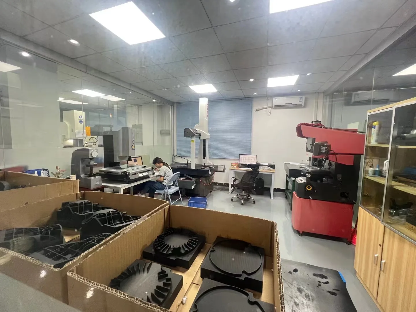
Finished-part dimensions depend on the selected resin, part geometry, tool layout, and processing conditions together. The resin datasheet can inform expected behavior, but it cannot determine a final molded dimension on its own. Fiber orientation, wall transitions, gate location, packing, cooling, and ejection can alter shrinkage and warpage.
The project should therefore lock down the assumptions used to review a critical tolerance:
- Resin grade and any reinforcement or filler.
- Nominal wall sections and orientation of critical features to flow.
- Tool layout, gate location, and cavity identification.
- Processing and cooling state used for the sample.
- Any post-molding conditioning before inspection.
A material or geometry change can invalidate an earlier tolerance assessment. For example, a fiber-filled resin may shrink differently along and across flow, changing a hole’s shape or location. Do not translate one supplier’s published shrink allowance into a universal capability number; manufacturer tables are tied to their own process and terms. Key takeaway: review each CTQ against the actual resin, geometry, tool, and sample condition.
What should a first finished-part inspection report capture?
A first finished-part inspection report for an injection molded part should connect each agreed CTQ to an actual result, method, sample identity, and disposition. It is a record of a specific part or sample under stated conditions; it is not a mold or steel inspection report. Agree the report’s scope before sampling so the supplier and buyer do not assume different deliverables.
A useful report structure includes dimensional and functional evidence where both answer separate acceptance questions:
| Report field | Why it matters |
|---|---|
| Characteristic ID and drawing revision | Connects the result to the requirement being checked |
| Nominal, limits, and actual result | Shows the measured outcome against the agreed specification |
| Sample, cavity, resin lot, and run condition | Defines what production state the sample represents |
| Equipment, fixture, datum, and method | Makes the measurement interpretable and repeatable |
| Deviation and disposition | Shows whether the part is accepted, corrected, or awaiting review |
If the purchase specification defines a formal first-article format, follow that agreed scope. Do not assume the same package is required for every molded part. Define the deliverable, sample quantity, and approval owner in the project requirements. Key takeaway: agree on a finished-part evidence package that matches the project and customer requirements.
How should measurement setup reflect molded-part behavior?
Injection molding tolerances can only be judged consistently when the part’s measurement condition is defined. State whether the part is free-state or supported, how datums are established, what fixture contacts are allowed, and when measurement occurs after molding. Include conditioning or environmental requirements only when the product specification or an agreed test method supports them.
A fixture should locate the part without forcing it into nominal shape. Thin walls, soft materials, and long unsupported spans can flex under clamping or probe pressure. Record the method and equipment, then check whether the instrument can resolve the tolerance with suitable uncertainty. The ISO 14253-1 decision-rule overview explains why measurement uncertainty matters when a result sits near a specification limit.
If two parties use different supports or datum schemes, their numbers may disagree even when both measured carefully. Make the setup part of the acceptance agreement. Key takeaway: define how the part is held and measured before comparing first samples.
How should near-limit measurement results be judged?
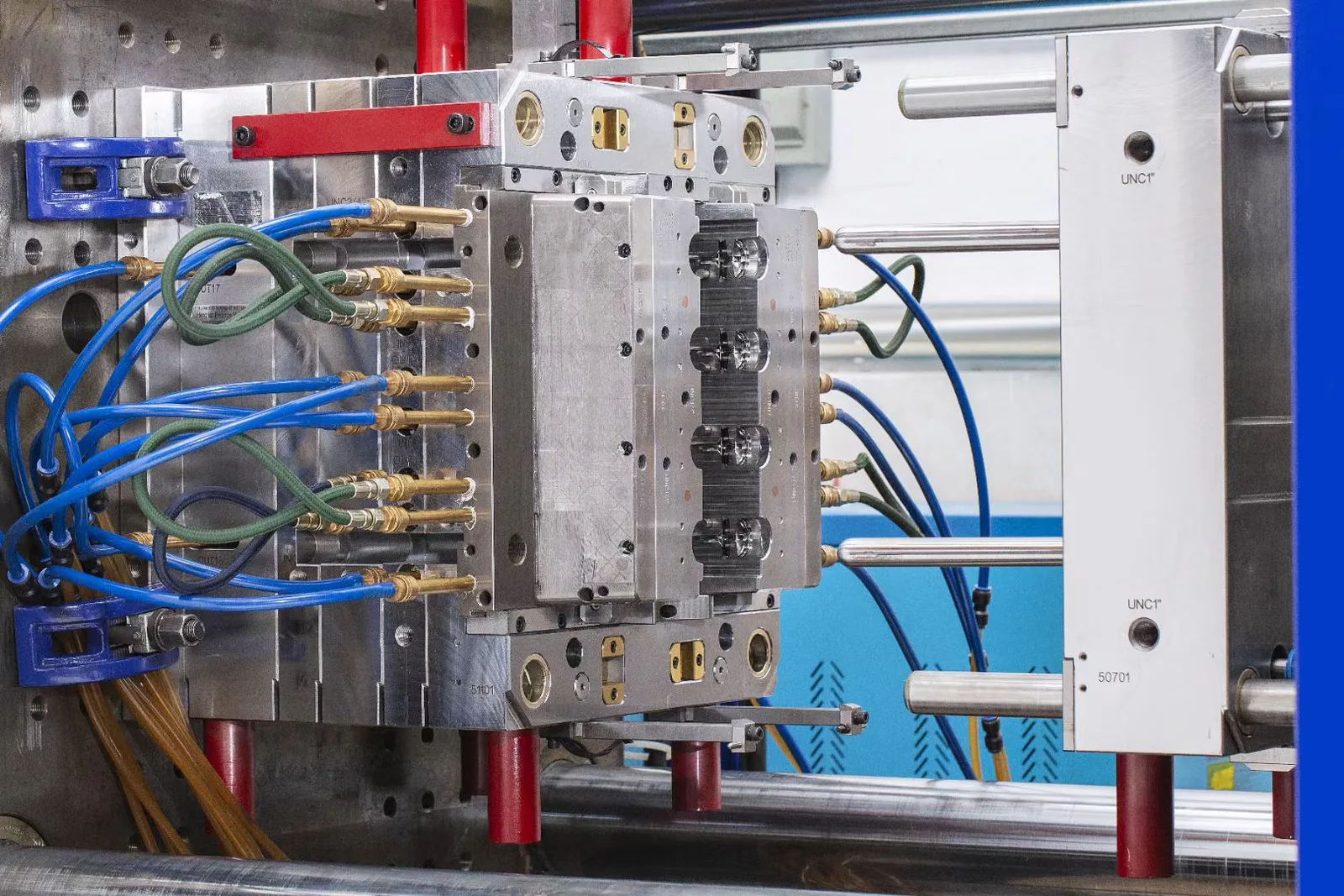
A measurement near a tolerance limit needs an agreed decision rule that accounts for measurement uncertainty. A reported value alone may not establish clear conformity when its uncertainty overlaps the specification boundary. ISO 14253-1 provides general geometrical product specification rules for this situation; it is not specific to injection molding.
Keep three ideas separate:
- Specification: the permitted range for an individual characteristic.
- Measurement result: the value reported for the inspected sample.
- Process capability: evidence about variation across a defined process and population.
One first-part result does not establish stable process capability. Conversely, a capability statistic does not replace a defined drawing requirement or acceptance decision for a sampled part. Agree the decision rule and escalation route before the data arrive. Key takeaway: define the rule for borderline results in advance, not during a supplier dispute.
What action should follow a first-shot miss on a critical characteristic?
For injection molding, a first-shot miss should trigger a documented review of the requirement, measurement setup, resin, tool, and process before anyone changes the part or tool. Confirm the drawing revision, sample identification, datum alignment, fixture, and instrument first. Then investigate material behavior, geometry, gate or cooling effects, and process settings as relevant.
The response should identify the cause and the affected CTQs. Possible outcomes include a measurement correction, process adjustment, tool modification, design revision, or an approved deviation. Each option changes cost, schedule, or product risk, so the buyer and supplier should agree who authorizes it and what evidence closes the action.
Avoid undocumented “tuning” that makes one sample pass while leaving the approved condition unclear. Recheck affected features after a change and retain the new condition with the results. Key takeaway: treat a miss as a controlled decision with a recorded cause and retest plan.
How should buyers distinguish first-part acceptance from ongoing process control?
First-part acceptance confirms a sample against agreed requirements; ongoing process control evaluates whether production remains consistent over time. Injection molding tolerances define feature limits, while run data and sampling plans address continuing variation. The two activities should connect, but they answer different questions.
Before release, agree which CTQs need routine monitoring, the sample frequency, the reaction plan, and what changes require renewed approval. A material substitution, tool repair, cavity change, or process-window adjustment may affect dimensions differently. Do not label a single inspected sample as proof that all future parts will conform.
The plastic shrinkage article provides background on dimensional change; this guide focuses on finished-part requirements and acceptance evidence. Key takeaway: define both the initial acceptance decision and the continuing control plan.
FAQ
- Do injection molded parts have one universal tolerance range?
- No. Tolerances depend on the function, resin, geometry, tool, process, and agreed measurement method. Supplier-published figures are specific to that supplier’s process.
- Is a mold machining tolerance the same as a molded-part tolerance?
- No. Mold machining describes tool dimensions; finished-part dimensions also reflect shrinkage, material behavior, geometry, and processing.
- Does one first-part inspection prove process capability?
- No. It documents results for inspected samples and stated conditions. Capability requires evidence across a defined process and population.
- Should every molded feature have a tight tolerance?
- No. Apply explicit limits where they protect fit, function, sealing, alignment, or another defined requirement. Unnecessary tight limits can increase cost and inspection work.
- What should be agreed before measuring a first molded sample?
- Agree the drawing revision, sample and cavity identity, resin and run condition, datum setup, fixture, measurement method, conditioning, and decision rule.
- Can a finished-part report replace mold inspection?
- No. A finished-part report checks molded parts against product requirements. Mold inspection evaluates the tool as an asset; they have different purposes.
Conclusion
A useful tolerance plan ties function, measurement conditions, and first-part evidence together before production release. Keep the requirements and acceptance rule specific to the project, then contact WOKE Molds to discuss a molded-part inquiry.