
Insert Molding Design Guidelines: 9 Essential Checks
Insert molding design guidelines should connect the insert’s function to its location, retention geometry, surrounding plastic, and validation plan. A metal feature embedded in a molded part can simplify assembly, but poor support or load transfer can lead to insert movement, pull-out, or cracking around the interface.
Use the drawing to define what the insert must do, then review how it will be held during molding and verified in the finished part. These insert molding design guidelines give the review a practical starting point; include the insert specification, resin, loads, and acceptance needs in a project inquiry through the metal insert molding service page.
Design the plastic and insert as one load-carrying interface. Specify how the insert is located, what loads it must resist, and how the finished part will be checked. Validate the combination of insert geometry, resin, and molding conditions rather than relying on a generic rule of thumb.
In short: a reliable insert-molded part starts with a defined load path and ends with evidence from representative finished parts.
Key points:
- Translate service loads into the insert retention and interface requirements.
- Design for repeatable location, plastic flow, and enough supporting material.
- Agree which dimensional, torque, pull-out, or environmental checks will approve the part.
When does insert molding solve a product problem?
Insert molding is useful when a preformed component must become an integrated feature of a plastic part. Common functions include repeated fastening, bearing support, electrical contact, or a durable mating surface. Whether molding the insert in is the right choice depends on the load, assembly sequence, available space, production volume, and service needs.
| Design situation | Possible benefit | Question to resolve |
|---|---|---|
| Repeated fastening | A durable threaded interface | What torque and service cycles are required? |
| Moving or mating component | A bearing or wear surface | What motion, lubrication, or temperature is expected? |
| Electrical connection | A contact incorporated into the part | What alignment, insulation, and test requirements apply? |
Compare molded-in inserts with post-mold installation only as a project decision. Post-mold heat, ultrasonic, or press-fit methods can simplify mold loading but add a later operation; molded-in features can integrate location but increase insert handling and tool considerations. Do not confuse this design decision with insert molding versus overmolding, which compares different material and process routes. Key takeaway: choose insert molding when integration serves a defined product or assembly need.
What loads should drive insert geometry and retention features?
Insert molding design guidelines should begin with the loads acting on the interface, because torque resistance and pull-out resistance are not the same requirement. A threaded insert may need to resist tightening torque, axial pull-out, back-out, shear, or bearing loads. Vibration and temperature cycling may also affect the joint over time.
| Load or failure mode | Design variables to review | Evidence to plan |
|---|---|---|
| Insert turns during assembly | Diameter, anti-rotation features, plastic engagement | Agreed torque-out test |
| Insert pulls from the part | Embedded length, undercuts, head, load direction | Axial pull-out test |
| Plastic cracks or splits | Edge distance, surrounding wall, boss transitions | Visual and section review; functional test as needed |
| Joint loosens in service | Fastener preload, vibration, thermal range | Application-representative evaluation |
SPIROL’s manufacturer guide to inserts for plastics describes how insert geometry and plastic engagement affect torque and pull-out behavior. Its guidance also shows why a feature that increases mechanical interlock can raise local stress. Choose geometry against the project’s load case and validate it in the intended resin and part design. Key takeaway: specify the failure mode and required evidence before choosing a retention feature.
How should an insert be located and supported in the mold?
In insert molding, the insert must be located repeatably in the cavity so that the finished feature has its intended position and orientation. The locating method may use a core pin, pilot, counterbore, nest, or other fixture feature selected for the insert design and tool layout. The correct arrangement depends on whether the insert is blind-ended, through-featured, threaded, or irregularly shaped. For thread geometry on molded parts, see the related molded threads design guide.
Before releasing the design, define:
- The datum or locating surface on the insert.
- The allowable position and angular variation in the finished part.
- How the insert is loaded and retained as the mold closes.
- How the design prevents plastic from entering threads or protected openings.
- Whether the insert can be loaded manually or needs automated handling.
A poorly located insert can shift, sit proud, or become partially blocked by flash. Those defects can create assembly rework even when the surrounding plastic looks acceptable. For projects requiring dedicated tooling, the insert injection mold page is a related service reference; tool selection still requires part-specific review. Key takeaway: treat insert location as a controlled datum relationship, not a visual placement step.
How much plastic should surround an insert?
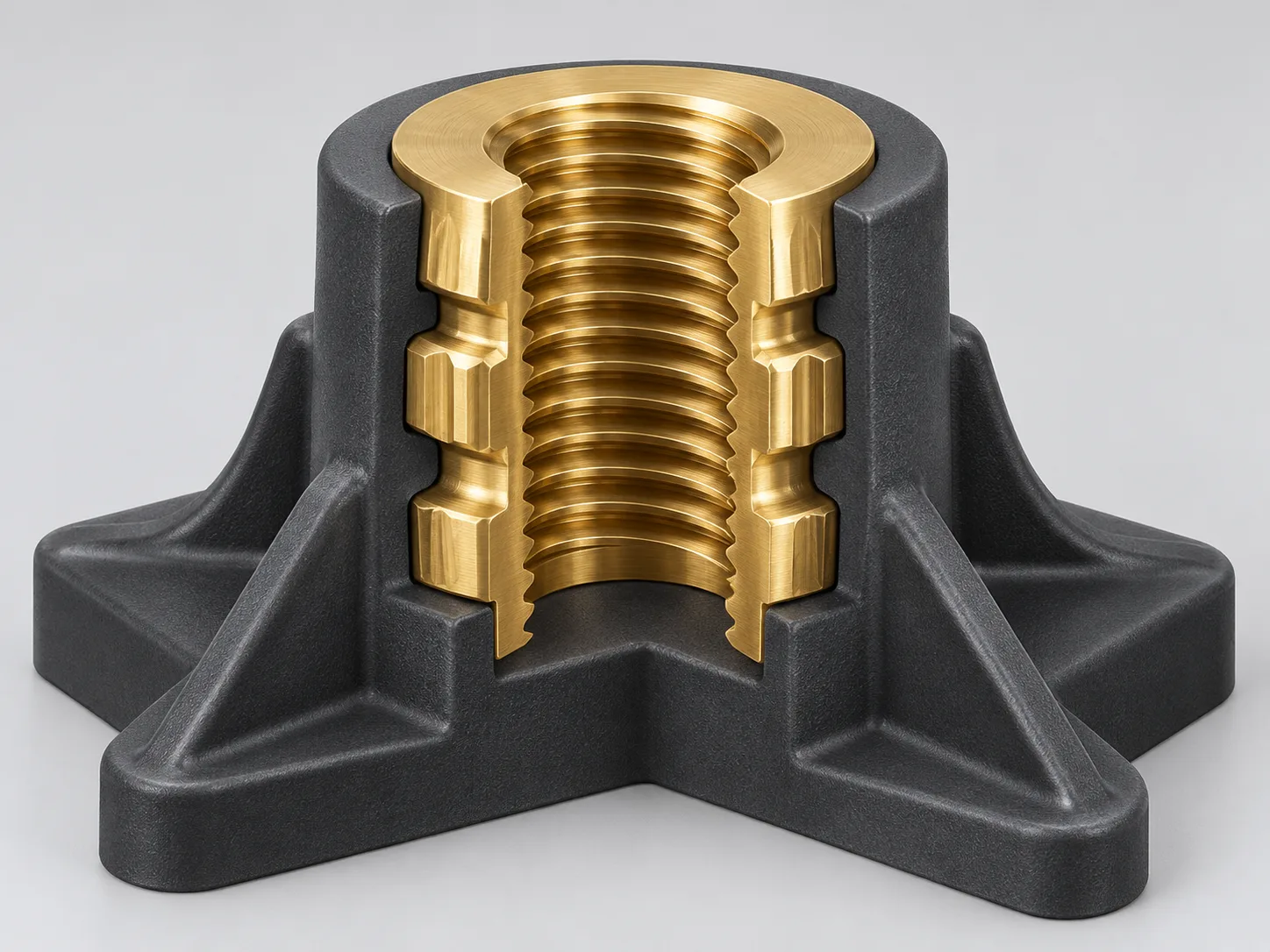
For insert-molded parts, the surrounding plastic must support expected loads without creating an unnecessarily thick or highly stressed region. Wall thickness, edge distance, boss shape, ribs, insert size, and the direction of force all influence the interface. There is no single wall or edge-distance value that is safe for every resin, geometry, and load.
A design review should compare the load path with the part’s available plastic envelope. A wider bearing surface may distribute load, while a sudden thick section can increase cooling variation or sink risk. Ribs or gussets may carry load toward nearby walls, but their geometry must still suit filling, cooling, and ejection. Avoid putting a rigid insert close to an unsupported edge when the service load can split that ligament.
Use a section view to confirm that the insert is surrounded where the design expects engagement. Then review the relevant dimensions with the selected resin and actual load direction. Key takeaway: size the surrounding plastic from load, geometry, and material behavior together.
How do resin shrinkage and metal-plastic expansion affect insert design?
Insert molding design guidelines should account for the fact that plastic and metal can change dimensions differently as temperature changes. During molding and cooling, shrinkage and thermal mismatch can create stress near the insert. The effect depends on the polymer, reinforcement, insert material and size, geometry, process conditions, and service temperature.
The Protolabs insert molding design guidelines provide supplier-specific examples of insert molding and material considerations. Treat those as that provider’s guidance rather than universal limits. Review the actual resin grade and its data, then consider both molding conditions and the part’s operating environment.
The larger or more constrained the insert, the more important it is to examine how the plastic transfers load around it. Avoid assuming that stronger mechanical locking always improves durability; greater restraint can also concentrate stress. Key takeaway: review the material pair and temperature range before freezing insert dimensions.
How can plastic flow leave weak retention, flash, or blocked features?
In insert molding, plastic must fill the intended retention geometry while leaving protected insert features usable. If flow does not engage grooves or knurls, the insert may have less retention than expected. If shutoffs do not seal, flash or plastic ingress can block threads, contact surfaces, or other functional areas.
A focused review can examine the following interface risks:
| Risk | Design or process review | Finished-part evidence |
|---|---|---|
| Incomplete engagement | Flow path and retention geometry | Cross-section or appropriate internal inspection |
| Flash at a protected feature | Shutoff and sealing surfaces | Thread/contact inspection |
| Air or material trap | Venting and local flow behavior | Visual or sectioned sample review |
| Insert movement | Insert support and gate approach | Position measurement on molded parts |
SPIROL recommends examining plastic flow into insert features when retention depends on those features. Use a cross-section or another suitable method during validation when the interface is hidden. Appearance alone cannot prove engagement. Key takeaway: identify hidden interface risks and choose evidence that can actually reveal them.
How should the gate and flow path protect insert position?
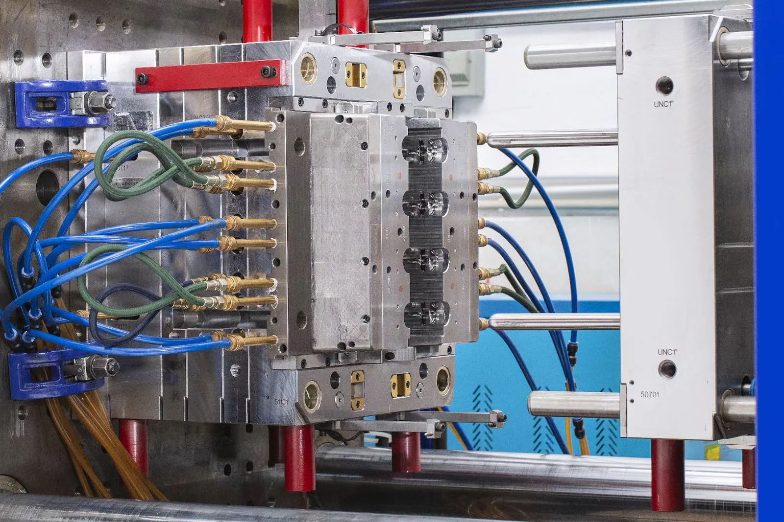
Insert molding gate and flow planning should reduce the chance that moving plastic displaces an insert or leaves a weakly filled region. Review the gate location, flow direction, insert support, cavity balance, and the features that must remain free of flash. The final choice depends on geometry and the molding system, so no single gate arrangement applies to every insert-molded part.
Where the insert is close to the gate or has a large exposed face, assess the force and direction of incoming material. The insert support must resist movement while still allowing the mold to close and the finished part to eject. A flow review or representative sampling can help expose risks before production intent is locked.
Avoid placing the insert so the first flow front strikes an unsupported surface when that could shift its location. Check the finished part for position, orientation, and any evidence of leakage around the insert. Key takeaway: review gate direction and insert support as a coupled design decision.
What tests should approve an insert-molded part?
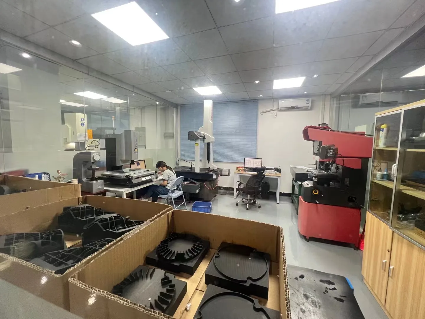
For insert molding, a part approval plan should verify the insert’s presence, position, orientation, exposed height, protected features, and required retention performance. Which tests are appropriate depends on how the part will be assembled and used. A torque test alone does not demonstrate axial pull-out strength, and a drawing check does not prove resistance to service conditions.
A practical acceptance plan can include:
- Dimensional checks for insert location and critical surrounding features.
- Visual checks for flash, cracks, incomplete encapsulation, or blocked threads.
- Torque-out or pull-out tests where those loads matter.
- Temperature, vibration, or environmental evaluation where required by the application.
- Sample identification by cavity, resin lot, and molding condition.
Agree the test method, sample quantity, load direction, conditioning, and pass/fail limit before testing. Use values from the product specification or customer-approved requirements; do not substitute a supplier’s typical value for the project’s acceptance criterion. Key takeaway: validate the finished interface under the loads that matter in service.
When should a buyer specify post-mold insert installation?
Post-mold installation may be preferable when it reduces insert loading in the mold or fits the assembly sequence, though it adds a later operation. Heat installation, ultrasonic installation, and press-fit methods each depend on the resin, boss design, insert geometry, and assembly requirements. Installation timing alone does not determine whether an insert can be replaced in service; that depends on the joint, access, and a validated removal method.
Compare the routes against four project questions: does the insert need to be integrated as the plastic forms, can the tool load and locate it reliably, what secondary operation is needed, and where should retention be validated? Molded-in designs require accurate loading and location. Post-mold methods add a separate installation step but can avoid insert loading during the molding cycle; assess the resulting tool and work-cell requirements for the actual part.
Discuss the tradeoff with the insert supplier and molding team before freezing the design. If field replacement is required, specify a removal and replacement method and validate it on the actual joint and surrounding part. If the molded-in interface is critical to product function, plan validation around the actual load. Key takeaway: choose the installation route around loading, tooling, process sequence, and verified service requirements.
FAQ
- What is the main design goal in insert molding?
- Integrate the insert so it stays located and transfers the required service loads without damaging the surrounding plastic or blocking protected features.
- Are knurled inserts always best for insert molding?
- No. Knurls can support retention, but the right geometry depends on torque, pull-out, plastic flow, resin, and the part’s load case.
- How do I prevent an insert from moving during molding?
- Define a repeatable locating and support method, such as a suitable pin or pilot, and review the gate and flow direction around the insert.
- Can a metal insert crack the plastic around it?
- It can contribute to stress when material behavior, geometry, shrinkage, or service temperature concentrates load. Review the material pair and validate the actual part.
- What should an insert-molded part inspection include?
- Check insert presence, position, orientation, protected features, surrounding plastic, and any agreed torque, pull-out, or environmental performance tests.
- When should I use a post-mold installed insert?
- Consider post-mold installation when avoiding insert loading in the mold or fitting a secondary operation suits the production sequence and the boss supports that method. Field replacement requires a separate removal design and validation; installation timing alone does not make a joint replaceable.
Conclusion
A sound insert-molded design makes the load path, insert location, plastic support, and acceptance evidence explicit before production. For a project-specific review, contact WOKE Molds with the part model, drawing, resin requirement, and expected insert loads.