
Injection Molding Gate Types: A Practical Design Guide
Injection molding gate types determine where resin enters a cavity and how that entry affects the gate mark, fill path, and trimming step. The right option depends on the part, resin, appearance requirements, and tooling design.
Before tooling release, review injection molding gate types against the part’s cosmetic and functional zones. A marked-up model gives the mold team a clear basis for discussing injection mold manufacturing.
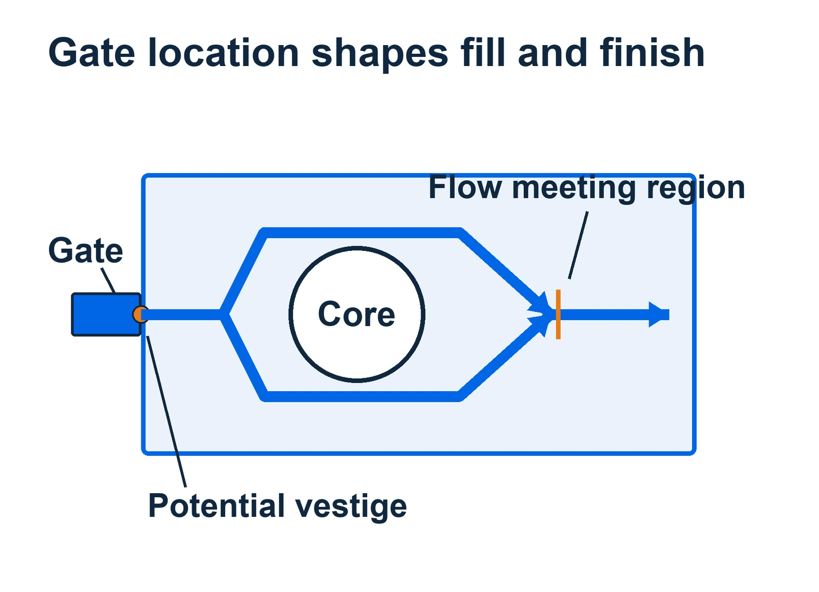
A gate is both a flow entrance and a feature the finished part must accommodate. Review its location against appearance, function, and trim access. Confirm the proposed entry point on the part model before tooling release.
In short: Compare gates by entry location, vestige, and removal method. Then check the candidate against the selected resin and part constraints.
Key points:
- Gate geometry, runner architecture, and valve actuation are related but separate design decisions.
- Gate location belongs in the same review as cosmetic, functional, and assembly zones.
- Agree on the allowed vestige and trial acceptance before approving the tool.
Which injection molding gate types should buyers compare first?
Injection molding gate types should be compared by entry location, vestige, and removal operation. Edge or tab gates and hot-tip gates are common examples; “pin gate” can describe a particular supplier design, so ask what geometry the term means on the proposed tool.
A gate is the final restricted entrance into the cavity. The runner brings melt to that entrance. Valve actuation is a control choice used with a hot-runner system, not a geometric gate type.
| Gate example | Typical review focus | Clarify with the supplier |
|---|---|---|
| Edge or tab | Entry along an edge or parting line | Allowed edge vestige and trim access |
| Hot tip | Entry at a selected surface location | Whether the witness or flow appearance is acceptable |
| Pin-gate example | The cited supplier describes a tunnel-fed ejector-pin/post arrangement | Confirm whether the proposed design uses that mechanism; it does not define all pin-point or tunnel gates |
Gate terminology varies by supplier. Protolabs’ examples distinguish the edge mark of a tab gate, the raised surface mark of a hot-tip gate, and its tunnel-fed ejector-pin arrangement, whose post is removed manually. Those examples are specific to that provider and do not define every pin-point, tunnel, or submarine gate. Its resin notes are also process-specific (Protolabs gate examples). Key Takeaway: Ask the moldmaker to show the actual gate passage and separation method on the tool or part drawing.
How should gate location balance flow, packing, appearance, and function?
Injection molding gate location should be reviewed against the part’s flow path, visible surfaces, functional features, and trimming access. A location that suits one design may not suit another.
Use a decision map rather than a preselected point. Mark acceptable witness areas, protected assembly/sealing features, and geometry constraints. Ask the supplier to show a candidate entry and state which project requirement it addresses.
A concise review sequence is: mark cosmetic and no-mark zones; identify assembly and sealing interfaces; show the proposed entry, resin, and trim method; then record unresolved tradeoffs for the mold trial.
This makes the decision reviewable without assuming a gate location guarantees a defect-free part. Key Takeaway: Approve a location only after the same model shows the entry point, protected features, and accepted vestige zone.
When is a central gate a poor choice for a long, narrow part?
For injection molding gate placement, a central gate can be a poor default for a long, narrow part because it may create different orientation and packing conditions along its length. Autodesk's Moldflow guidance contrasts this geometry with symmetric parts and discusses evaluating end entry; the appropriate choice still depends on the part and material.
| Geometry under review | Compare | Confirm during validation |
|---|---|---|
| Symmetrical part | Central versus balanced entry points | Fill pattern and weld-line location |
| Long, narrow part | Central versus end entry | Orientation and dimensional behavior along the length |
| Asymmetric geometry | Candidate locations and flow path | Trial-part performance against agreed requirements |
Treat this comparison as a design question, not a universal rule. The Moldflow page is engineering guidance rather than a guarantee; test the selected arrangement with suitable model inputs and molded parts (Autodesk Moldflow gate-location guidance). Key Takeaway: For a long, narrow part, ask the tool team to compare end entry with the center option before fixing the gate position.
How does gate style affect the vestige, trimming, and cosmetic surface?
Injection molding gate style affects where the remaining vestige appears and how it is removed. Define the permitted mark and trim method before approving a gate on or near a visible surface.
Use the approved model to identify where the mark will remain and what operation removes it. If manual trimming is not acceptable for the part, state that constraint before tool release.
Review each proposed gate against four acceptance needs: which face may show the mark, how the gate will be separated and trimmed, whether a vestige can affect assembly or sealing, and how the finish will be checked. Confirm whether the proposed tool action removes the gate automatically or requires a later trim operation.
Key Takeaway: Put the allowed witness zone and gate-removal method on the approved model or drawing.
How can gate placement affect a load-bearing or sealing area?
For a load-bearing or sealing feature, start with its function and acceptance condition, then review gate location and trim access against that requirement. Identify the sealing face, assembly interface, or expected load direction on the drawing. Ask the tool team to show how the proposed entry and remaining vestige relate to it.
If a candidate conflicts with a critical feature, compare alternatives and record the tradeoff for the design review. Keep the decision tied to the part requirement rather than moving the gate mark in isolation.
Key Takeaway: Put functional zones on the same marked-up model used to approve the gate and trim plan.
How should resin reinforcement affect the gate discussion?
Gate selection should account for resin reinforcement because the exact grade and flow passage can constrain practical gate geometry. Do not transfer a gate assumption from an unfilled resin to a reinforced grade without review.
Gate suitability can change with resin and reinforcement. The Protolabs examples cited above show that a gate recommendation is process- and material-dependent. Confirm the selected grade, gate passage, and toolmaker’s recommendation for the actual part.
Record the resin designation and allowed substitutions in the RFQ. If material selection is open, list the candidates so the supplier can identify any gate-related limits before tool release.
Key Takeaway: Check gate suitability against the exact grade and reinforcement before locking the design; a material change can invalidate the earlier review.
When should a buyer request mold-filling analysis for gate placement?
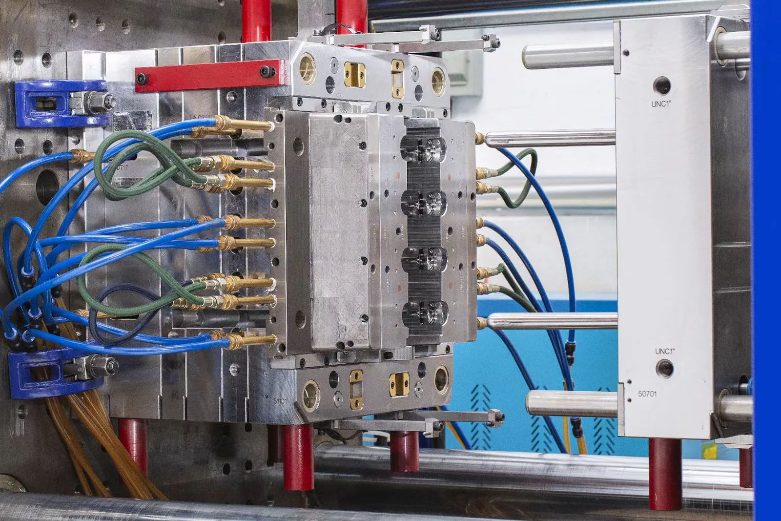
Request a comparison when the injection molding gate location is uncertain because of competing part requirements. Before analysis, prepare the current model, candidate resin data, protected features, and the decision to resolve. Ask which alternatives will be compared and what trial evidence will confirm the choice.
| Handoff item | What to provide or ask |
|---|---|
| Geometry | Current model and drawing revision |
| Material | Exact grade or candidate grades |
| Constraints | Cosmetic and functional zones |
| Decision | Gate options to compare and the question being answered |
| Validation | Trial observation that will confirm the choice |
This handoff keeps the analysis tied to a buyer decision instead of asking for a generic simulation. Key Takeaway: Request analysis when it can distinguish real alternatives, and agree in advance how the result will be checked on parts.
What information should an RFQ include to review gate placement?
An injection molding gate-placement RFQ should include the part geometry, resin, cosmetic boundaries, functional features, and trimming requirements. These inputs let the supplier explain the proposed gate and its tradeoffs.
Include the current model and drawing, resin grade or candidates, allowed gate-mark areas, sealing and loaded features, assembly interfaces, and inspection criteria. State known production or tooling assumptions and identify open decisions instead of filling gaps with guesses.
For related design context, see the hot-runner and cold-runner comparison and mold-flow analysis overview. The gate location still needs its own part-level review.
Key Takeaway: Ask the supplier to mark the gate, vestige, and trim operation on the model before approving the tooling design.
How should gate placement be accepted during a mold trial?
Injection molding gate placement should be accepted against the agreed location, vestige, trim method, and part requirements during a mold trial. The trial shows whether the proposed mark and removal operation work on molded parts.
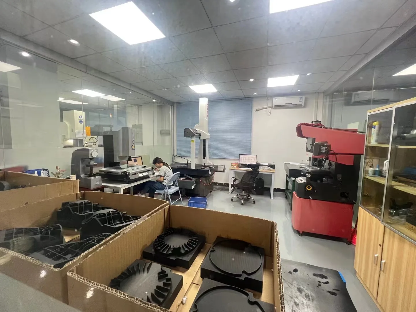
Compare parts with the approved model: check the vestige zone, trim consistency, appearance, assembly, sealing, and relevant dimensions. Record the resin grade and lot, cavity where applicable, gate location, and deviations that need disposition.
On trial parts, check whether the mark is inside the approved zone, trimming is consistent, assembly and sealing remain acceptable, and results are consistent across cavities. Record any deviation with the cavity and agree on disposition before release.
For a project discussion, share the current part model and gate constraints through the project inquiry page. Key Takeaway: Close gate approval with a documented part-level review, not only a tool drawing sign-off.
What are the core rules of injection molding gate design?
Gate design sets the size, shape and position of the opening where melt enters the cavity. Good gate design fills the part from thick to thin sections, packs it fully and freezes at the right time.
- Size: large enough to pack the thickest wall, small enough to freeze and trim cleanly.
- Position: into the thickest section, away from cosmetic, sealing and load areas.
- Land length: short, so pressure loss stays low.
- Flow direction: against a wall or pin to avoid jetting.
- Wear: hardened or replaceable gate inserts for glass-filled resins.
For example, a 1.5 mm wall PC housing gated with a 0.6 mm pin-point gate may short-shot near the far rib; increasing the gate and moving it toward the thick boss lets the part pack. See our guide to injection molding tool design and the cold runner guide for runner and gate sizing.
Key Takeaway: In practice, review gate size, position and wear together in one gate design decision.
FAQ
- What are the most common injection molding gate types?
- Common examples include edge or tab and hot-tip gates. One supplier’s pin-gate example uses a tunnel-fed ejector-pin arrangement; it does not define every tunnel, submarine, pin, or point gate.
- Where should an injection molding gate be located?
- Choose a location by reviewing flow path, allowed vestige zones, functional and assembly features, trim access, resin, and tooling constraints together.
- Does gate type determine the runner system?
- No. Runner architecture describes how melt reaches the gate; gate geometry describes the final entrance into the cavity.
- Can a gate mark be placed on a cosmetic surface?
- It can be considered when the visible mark and any local appearance effect meet the agreed cosmetic criteria. A concealed area may be preferable when flow and tooling permit.
- Does glass-filled resin change gate selection?
- It can. Check gate passage and geometry against the exact reinforced grade; examples from one molding supplier are not universal rules.
- What should I send with a gate-placement RFQ?
- Send the current model and drawing, resin grade or candidates, cosmetic map, critical features, allowed vestige locations, trim/access requirements, and inspection criteria.
Conclusion
Gate selection connects how melt enters the cavity with the mark and trimming operation on the finished component. Share the part geometry, resin, cosmetic map, and functional constraints through the WOKE Molds project inquiry page to discuss the tooling review.