
Injection Mold Venting: 9 Essential Tooling Checks
Injection mold venting gives displaced air and process gases an escape path as melt fills the cavity. Good vent placement and a clear route to the outside help the mold fill consistently, but vent dimensions must match the resin and tool.
When injection mold venting is a concern, inspect the air-escape path before changing machine settings. Include vent access in the injection mold manufacturing review.
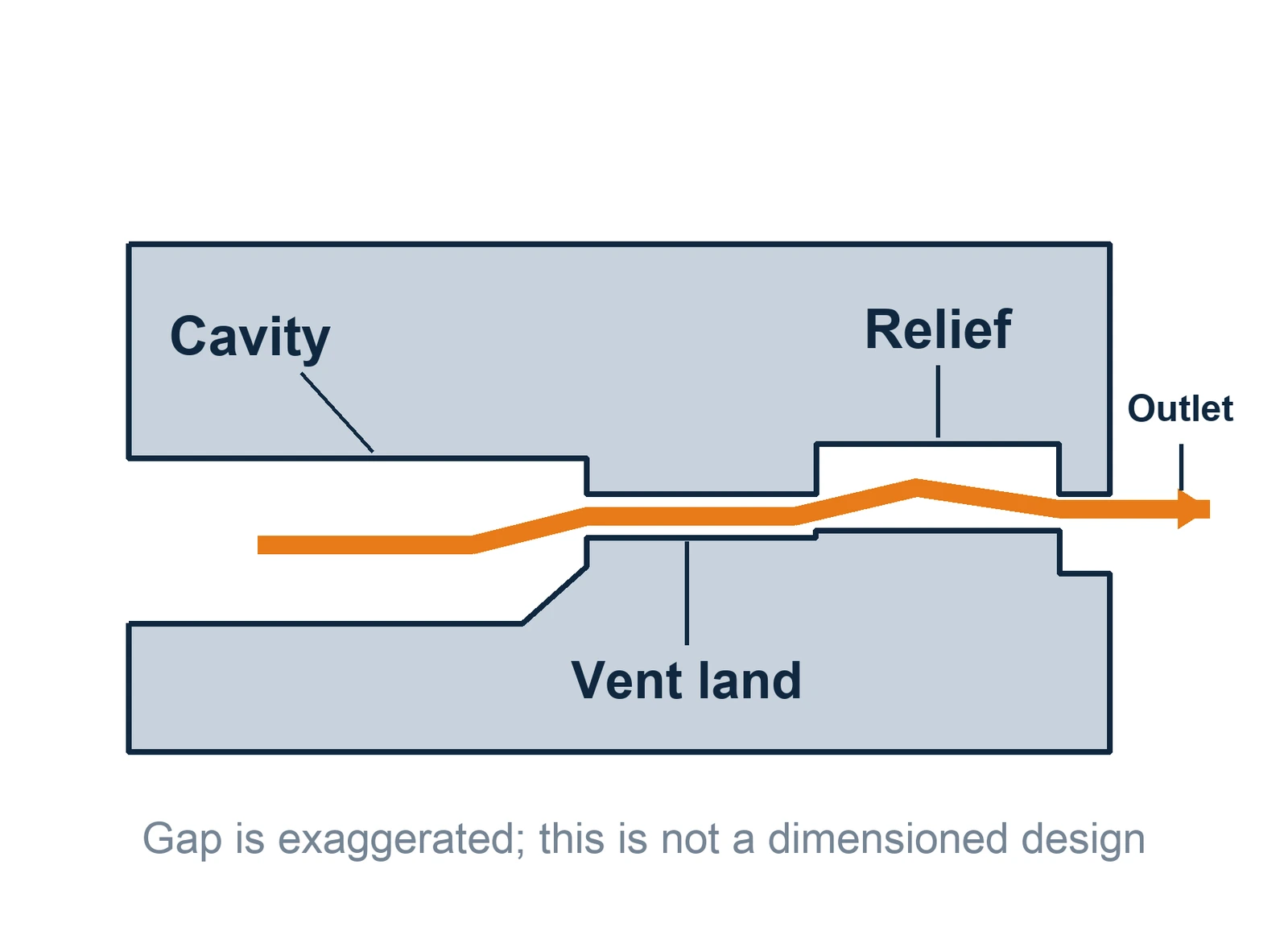
Vents work as a path: gas must reach an opening, pass through the vent land, and leave through a relief or outlet. A blocked or misplaced path cannot be fixed by specifying a depth alone. Review location, resin, cleaning access, and trial evidence together.
In short: Review where air is trapped, where it can escape, whether the vent suits the resin, and how it will be cleaned. Use simulation and trial evidence to refine the location instead of copying a universal dimension.
Key points:
- Last-to-fill regions and flow-front meeting points deserve focused vent review.
- Vent depth, land, relief, and outlet form one route; the land is only one part of the system.
- Resin-specific supplier data, mold design, process settings, and maintenance all affect results.
What does injection mold venting do as the cavity fills?
Injection mold venting lets the air and gases displaced by the melt leave the cavity, runner, and sprue. If that gas cannot escape, filling may be incomplete and the part may show burn marks or poor appearance.
As melt advances, it pushes air toward the vent. The route runs from the cavity through a controlled land into a larger relief or channel. A shallow land without a connected exit is incomplete.
Venting interacts with the rest of the molding cycle. The cavity fills and packs while heat moves into the mold; the melt skin can begin to solidify during filling. Cooling is not a separate event that begins only after the gate freezes. Airflow, fill speed, packing, gate location, and heat transfer therefore need to be considered in context.
DME identifies short shots, poor surface appearance, and weak weld lines among issues associated with inadequate venting. These are clues to investigate, not proof that the vents are the only cause (DME venting overview, Eastman processing and mold design guidelines). Key Takeaway: Treat venting as a complete gas-exit path that operates during filling, not a single groove dimension.
Where should vents be placed in an injection mold?
Injection mold venting should target areas where gas is likely to collect, especially last-to-fill regions and flow-front meetings, with each vent connected to a usable outlet. The exact map depends on the part, gate, resin, and flow pattern.
The parting line is one option; ribs, pockets, cores, runner ends, and ejector features can trap gas elsewhere. DME recommends last-fill and weld-line review. Eastman notes that a gate change can shift the last-fill area toward better venting.
Use a fill map to mark the gate, flow direction, front meetings, predicted last-fill areas, deep ribs or pockets, and each route to an outlet. Confirm that land and outlet can be inspected and cleaned.
| Potential location | What to examine | What the review should establish |
|---|---|---|
| Parting line | Last-fill and weld-line areas | Vent position and a connected relief route |
| Rib, pocket, or core | Local air trap and access | Whether pin, porous, or another vent path is suitable |
| Runner end or cold slug area | Gas at the feed system end | Whether the runner has a clear escape route |
| Gate-adjacent region | Flow restriction and local fill | Whether venting or gate position needs review |
A predicted air trap is a design clue; trial evidence should confirm whether the actual fill sequence matches the model. Key Takeaway: Locate vents from the flow path and likely gas traps, then check that every vent can actually discharge.
How can trapped air affect molded parts?
Injection mold venting can affect short shots, burn marks, appearance, and weld-line strength when gas cannot escape as the cavity fills. A symptom alone does not distinguish venting from material, gate, or process causes.
Compressed gas in an isolated region can resist the incoming melt. Local heating and gas buildup may contribute to burning, while a stalled or poorly joined flow front may leave an incomplete or weak region. The specific result depends on where gas is trapped and the process conditions.
Use symptom location as a clue: a mark at last fill differs from a streak near the gate. Compare the defect with the predicted flow and vent map before changing several settings at once.
For weld-line concerns, assess both flow-front meeting points and vent access. The existing weld-line troubleshooting guide covers the broader defect intent; this venting review focuses on whether gas can escape at the meeting location. Key Takeaway: Use the location and repeatability of a defect to guide investigation, not to declare venting the cause.
What makes a vent path more than a vent depth?
Effective mold venting includes the shallow land, deeper relief, and a clear route for gas to exit the tool. Specify and inspect those connected features together.
The vent land is the shallow section nearest the cavity. The relief opens into a larger channel so gas can move away without leaving an uncontrolled cavity opening. If the relief is blocked, ends inside the tool, or cannot be cleaned, an acceptable land depth alone does not establish a working route.
Check that the land is in the intended cavity location, the relief connects to an exit, deposits can be removed, and the route is serviceable. Verify dimensions against the specific resin and mold standard.
Some mold designs use a vented ejector pin or porous insert for a location that cannot easily vent across the parting line. These still need a downstream gas path and maintenance plan. Key Takeaway: Draw the full route from cavity to outlet; the shallow opening is only one segment.
When are parting-line, ejector-pin, or porous vents useful?
Injection mold venting can use parting-line, ejector-pin, or porous paths; the choice depends on the trapped-air location and service access. None is the universal choice for every feature.
A parting-line vent may suit an accessible perimeter or last-fill area; a vented ejector pin may serve a rib or pocket below it. Porous material can vent a local trap but may clog. DME also lists dynamic and vacuum-based approaches for specific applications.
| Approach | Possible fit | Tradeoff to review |
|---|---|---|
| Parting-line vent | Accessible edge or end-of-fill area | Must connect to relief and remain within the resin/tool limits |
| Vented ejector pin | Feature below the parting line | Pin fit, wear, and cleaning access need attention |
| Porous insert or plug | Local trap where a conventional vent is difficult | Clogging, service access, and replacement plan |
| Vacuum or dynamic system | Application with a documented gas-removal constraint | Added system, controls, and maintenance scope require supplier evaluation |
DME is a component supplier and describes product categories; this table compares design approaches, not product endorsements or WOKE Molds capabilities. Key Takeaway: Pick a vent method to suit the trapped location and service route, then confirm it with the moldmaker and resin supplier.
How should vent depth be chosen for a resin and part?
Choose injection mold vent depth from the exact resin supplier's current guidance and the tool design requirements, then validate it in trials. A number from another polymer is not a universal specification.
Eastman's processing guide gives Eastman-polymer starting examples: approximately 0.0005–0.001 inch for small parts or vents close to the gate, and 0.001–0.0015 inch for larger parts, with a 3–6 mm land before a larger outlet channel. Those dimensions are explicitly tied to molds designed for Eastman polymers; they should not be copied for a different resin or used as a WOKE Molds tolerance.
| Source context | What the cited source supports | How to apply it |
|---|---|---|
| Eastman polymers | Example vent-depth ranges and land length in Eastman's guide | Treat as Eastman-specific starting guidance; check current grade instructions |
| Other resin or unknown grade | No universal dimension is established here | Request the grade-specific supplier recommendation and tooling requirement |
| Trial part shows flash or persistent gas marks | The selected setup needs investigation | Recheck material, vent geometry, process, and actual location before changing depth |
Do not deepen a vent without checking flash risk and material behavior. Resin, part dimensions, location, land, relief, and fill profile all matter. Key Takeaway: Record the source and grade behind every numeric vent target, then confirm the actual tool and trial parts.
How should vent cleaning and maintenance be planned?
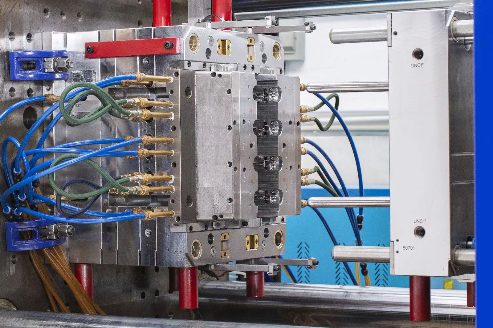
Plan mold-vent cleaning around vent type, deposits, and access; inspect when a recurring defect or process change suggests a blockage. A vent that was correctly designed can become ineffective if its route accumulates residue.
DME notes that ejector-pin vents may need regular wiping and that porous plugs may need cleaning or replacement when clogged. Eastman also advises checking and cleaning vents regularly. These are useful maintenance prompts, not a universal daily interval for every tool; the production team should set the interval from actual resin, cycle, and observed fouling.
Review access to the land, relief, ejector pin, or porous insert. Agree on permitted cleaning and how wear or replacement is recorded. Where possible, avoid a layout requiring unnecessary disassembly for routine service.
A short maintenance record can include tool ID, vent location, observed deposit, cleaning action, and whether the part symptom changed after service. Key Takeaway: Define how a vent will be inspected and cleaned before production, then set frequency from evidence on the actual tool.
How can a team distinguish venting trouble from a process-setting issue?
For injection mold venting trouble, compare the defect pattern with the fill sequence and vent condition before blaming tooling or process. A short shot or burn mark can have more than one cause.
Record where the defect occurs, whether it repeats by cavity, last-fill location, and whether the vent connects to an outlet. Then review material condition, gate/runner path, fill profile, and machine settings with the process owner. Change one variable at a time.
| Observation | First evidence to review | Follow-up comparison |
|---|---|---|
| Short shot at a consistent last-fill zone | Fill map, vent cleanliness, and outlet route | Compare a controlled process change or vent-location trial |
| Burn mark near a local pocket | Local trapped gas and vent path | Check material/process conditions and pocket geometry |
| Weak weld area | Flow-front meeting location and local venting | Compare gate position and fill pattern |
| Symptom appears after material or process change | Grade, drying/handling record, and process settings | Verify the vent map still suits the changed condition |
Mold-filling analysis can help predict possible air traps; a short-shot study can help locate critical areas after the tool is built. See the mold-flow analysis overview for the adjacent simulation topic. Neither method replaces inspection of the physical vent route. Key Takeaway: Test one cause at a time using defect location, vent condition, and fill evidence.
What venting details should a buyer request in a tooling review?
A tooling review for injection mold venting should show vent locations, land-to-relief transition, exit route, resin basis, and maintenance access. Those details make the gas path and its limits reviewable before production.
Provide the part model, resin grade or candidates, gate location, cosmetic/functional zones, and applicable mold standard. Ask for vent locations at predicted last-fill and front-meeting areas. For simulation or short-shot evidence, confirm the geometry, material data, and process assumptions.
The review can also record the agreed vent inspection and cleaning method, who owns it, and what trial observation triggers a tooling adjustment. Do not assume a tooling quote includes simulation, a particular vacuum system, or a measured moisture/dryer capability unless the supplier states it in the project scope.
For a project discussion, send the current model and relevant material information through the project inquiry page. Key Takeaway: Make vent location, complete outlet path, resin-specific dimensions, and service access visible in the mold approval record.
FAQ
- What is venting in an injection mold?
- It is the designed route that lets air and process gases leave the cavity, runner, or sprue as the melt fills the mold.
- Where should injection mold vents be placed?
- Review last-to-fill regions, flow-front meeting points, runner ends, and local traps such as ribs or pockets, then ensure each route reaches a usable outlet.
- Can poor venting cause burn marks or short shots?
- Inadequate venting can contribute to burns, short shots, poor appearance, or weak weld areas, but each symptom needs a broader process and tooling check.
- How deep should an injection mold vent be?
- Use current, grade-specific resin guidance and the mold design requirements. Published dimensions for one resin family are not universal settings.
- Are ejector pins used for mold venting?
- A vented ejector pin can provide a path from a feature below the parting line, provided its fit, outlet, wear, and cleaning needs are addressed.
- How often should mold vents be cleaned?
- Set the interval from the actual resin, tool, deposits, and production evidence. Inspect when recurring symptoms or process changes suggest a blockage.
Conclusion
A usable vent design connects the gas-trap location to a maintainable exit path and respects the selected resin's processing limits. Share the part model, gate plan, and material grade through the WOKE Molds project inquiry page to discuss the tooling review requirements.