
Ejector Pin Marks: Causes and How to Prevent Them
Ejector pin marks are the small round or shaped witness marks left where ejector pins push a molded part out of the mold. A light, flush mark on a hidden surface is normal. Problems start when the marks are raised, sunken, glossy, whitened or surrounded by flash, or when they appear on a cosmetic face.
Most of these problems are decided before the mold is built. For example, a housing with too little draft and only four small pins needs high force to eject, so each pin leaves a white stress mark. The same part with more draft, larger pins and a stripper on the deep wall ejects cleanly. In this guide, we explain what causes ejector pin marks, how ejector pin layout reduces them, and which drawing notes help buyers control them. For the wider list of molding problems, see our guide to injection molding defects and troubleshooting.
Ejector pin marks are witness marks left on a molded part by the ejector pins that push it out of the mold. Normal marks are small, flush and on non-cosmetic surfaces. Defective marks are raised, recessed, whitened, glossy or flashed. They are caused mainly by high ejection force, poor draft, too few or too small pins, wrong pin height, wear and process settings, and they are best controlled by ejector layout during mold design.
In short: plan where the pins go and how hard they push, and the marks stay small and hidden.
Key points:
- Placement: put pins on hidden faces, ribs and bosses, never on cosmetic surfaces.
- Force: good draft and enough pin area keep stress marks away.
- Fit: correct pin height and clearance prevent bumps, dents and flash rings.
What Are Ejector Pin Marks?
Ejector pin marks are the imprints of the ejector pin faces on the molded part. Every pin that touches the part leaves some mark, because the pin face and the surrounding steel are never perfectly identical.
Acceptable marks are usually:
- Flush or very slightly recessed
- Free of flash around the edge
- On the B-side or other non-cosmetic surfaces
- Similar in gloss to the surrounding surface
Defective marks are usually:
- Raised or sunken because the pin height is wrong
- White or stressed because the ejection force is too high
- Ringed with flash because the pin clearance is worn or too large
- Shiny or dull compared with the textured surface around them
Key Takeaway: Define on the drawing which ejector pin marks are acceptable and where. That avoids arguments at sample approval.
What Causes Ejector Pin Marks on Molded Parts?
Ejector pin marks on molded parts are caused by the combination of how strongly the part grips the core and how the pins push it off. The main causes are:
- Insufficient draft, which increases friction during ejection
- Too few or too small pins, which concentrate force on small areas
- Wrong pin height, which presses bumps or dents into the surface
- Worn pins or holes, which let plastic flow into the gap and form flash
- Overpacking, which makes the part grip the core harder
- Ejecting too hot, before the part is stiff enough to resist the pins
- Rough or undercut core surfaces, which hold the part
For example, a deep box with 0.5° of draft on a textured surface can need several times more ejection force than the same box with 2° of draft. Our draft angle guidelines explain how much draft each texture needs.
Key Takeaway: Most ejector pin marks are a force problem. Reduce the force needed, then spread it over more area.
How Does Ejector Pin Layout Reduce Visible Marks?
Ejector pin layout reduces visible marks by placing pins where marks do not matter and where the part resists ejection most. A good layout pushes the part evenly, close to the features that grip the core.
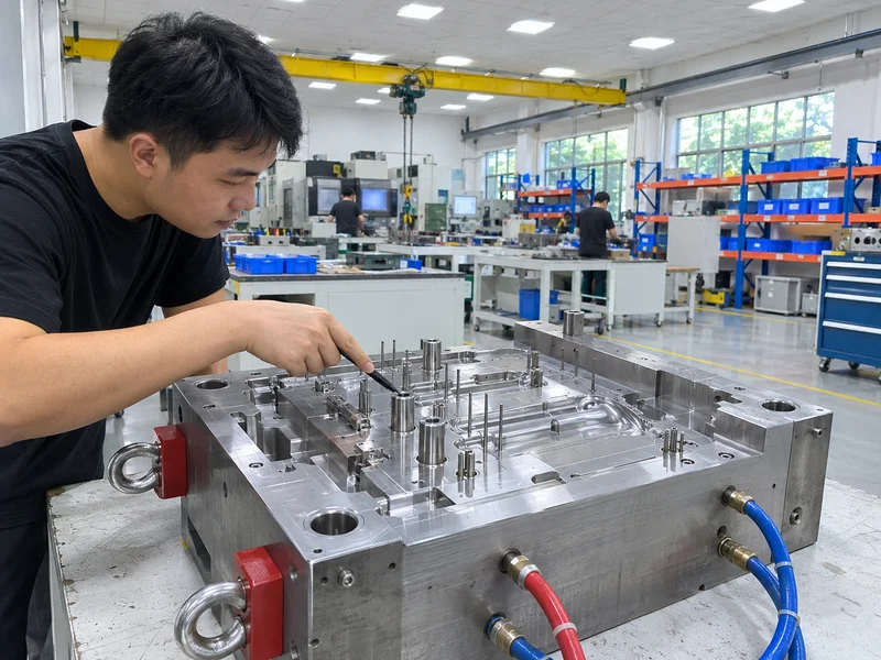
Layout rules that work:
- Push near the grip: place pins next to deep ribs, bosses and walls.
- Balance the force: spread pins so the part lifts evenly without tilting.
- Use hidden surfaces: put pins on the inside, on ribs or on mounting pads.
- Use ribs and bosses: blade pins on rib ends and sleeves around bosses.
- Keep away from thin areas: thin walls bend and show marks more easily.
The ejector pins themselves are standard components. We build molds with HASCO, Meusburger, STRACK, DME, CUMSA or MISUMI standard parts, according to the customer’s standard. Pin dimensions and tolerances for moulding tools are also covered by ISO standards. Our article on injection mold components shows how the ejector system fits into the mold.
Key Takeaway: Review the ejector layout at DFM, with the cosmetic surfaces marked. Moving a pin on paper costs nothing; moving it in steel does.
Which Ejection Methods Leave the Least Visible Marks?
The ejection methods that leave the least visible marks spread force over a larger area or push on edges instead of faces. The best choice depends on part shape.
| Ejection method | How it works | Best for | Mark left |
|---|---|---|---|
| Round ejector pins | Pins push on flat faces | General parts | Round witness marks |
| Blade ejectors | Flat blades push on rib ends | Thin ribs | Small slot marks on ribs |
| Ejector sleeves | Sleeves push around bosses | Bosses and core pins | Ring on the boss end |
| Stripper plate or ring | Plate pushes the whole edge | Round cups, caps, thin walls | Almost none on faces |
| Air ejection | Air breaks the vacuum | Deep cups, lids | Small valve mark |
For example, a thin round cap ejected with three pins can turn white at each pin. A stripper ring pushes on the whole rim and leaves the top surface clean. Air ejection, covered in our guide to parting line injection molding, helps deep parts that hold on by vacuum.
Key Takeaway: For cosmetic or thin parts, ask whether a stripper, sleeve or air ejection can replace face pins.
How Do Pin Height and Clearance Affect Ejector Pin Marks?
Pin height and clearance affect ejector pin marks by changing the surface step and the risk of flash. Even a perfect layout fails if the pins sit too high, too low or too loose.
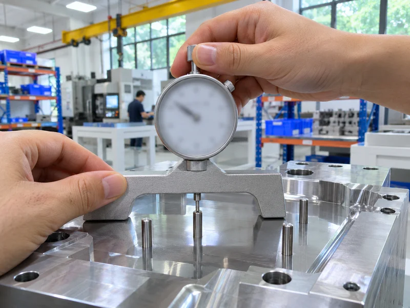
- Pin too high: pushes a dent into the part.
- Pin too low: leaves a raised boss on the part.
- Clearance too large: plastic flows into the gap and forms a flash ring.
- Clearance too small: pins gall, stick or break as the mold heats up.
Low-viscosity resins, such as PA and PP, flow into small gaps more easily than ABS or PC. Therefore, they need tighter pin fits. Worn pin holes also open up with time, so a mold that was clean at T1 can start flashing after many cycles. Regular mold maintenance catches this before parts are rejected.
Key Takeaway: Specify the allowed step at pin marks on the drawing, and check pins and holes during maintenance.
Which Process Settings Make Ejector Pin Marks Worse?
Process settings make ejector pin marks worse when they increase the grip on the core or eject the part before it is stiff. Process changes can reduce marks, but they rarely fix a weak layout.
- High packing pressure: the part shrinks tighter onto the core.
- Short cooling time: the part is still soft when the pins push.
- High mold temperature on the core: the part grips longer.
- Fast ejection speed: a sudden push stresses the surface.
- Long ejection stroke: the part bends at the end of travel.
For example, slowing the first part of the ejection stroke often removes white stress marks. Reducing packing pressure can also help, but only if it does not cause sink marks elsewhere.
Key Takeaway: Use process settings to fine-tune marks, not to rescue a mold with too little draft or too few pins.
How Should Drawings Specify Ejector Pin Marks?
Drawings should specify ejector pin marks by area and by allowed condition. A clear note avoids a different interpretation at the supplier and at incoming inspection.
A useful drawing note covers:
- Allowed areas, such as “ejector marks permitted on B-side only”
- Forbidden areas, such as cosmetic A-surfaces and sealing faces
- Allowed step, such as flush to slightly recessed, with a stated limit
- Flash, such as no flash permitted at ejector marks
- Appearance, such as no stress whitening
For example, a note such as “Ejector marks on B-side only; flush to 0.1 mm recessed; no flash or whitening” gives the toolmaker clear targets. Agree the exact values with your supplier, because they depend on the resin and the surface. Our quality control and inspection process checks cosmetic criteria against the agreed standard.
Key Takeaway: If ejector pin marks matter, put them on the drawing. “No visible marks” without a defined area cannot be checked.
How Do You Fix Ejector Pin Marks on an Existing Mold?
You fix ejector pin marks on an existing mold by first finding which type of mark you have, then changing the process, the pins or the steel.
- Inspect the mark: dent, bump, whitening, gloss or flash.
- Adjust the process: slower ejection, longer cooling, lower packing.
- Correct pin height: grind or replace pins to the right length.
- Replace worn pins: restore the fit to stop flash rings.
- Polish the core: reduce friction on deep walls.
- Add or enlarge pins: spread force where the part sticks.
- Change the method: add sleeves, blades or a stripper where needed.
Steps 1–4 are quick. Steps 5–7 change the mold steel and may need a new trial. Therefore, they should be planned with the part owner.
Key Takeaway: Fix the cause, not the symptom. A process change that hides marks today may fail when the mold warms up.
FAQ
- Q: What are ejector pin marks?
- They are witness marks left on a molded part where the ejector pins push it out of the mold.
- Q: Are ejector pin marks a defect?
- Not always. Flush marks on hidden surfaces are normal. Raised, sunken, whitened or flashed marks, or marks on cosmetic faces, are defects.
- Q: How do you prevent ejector pin marks?
- Use enough draft, place pins on hidden faces near ribs and bosses, use enough pin area and set the correct pin height.
- Q: Why do ejector pin marks turn white?
- Whitening is stress from high ejection force, often caused by low draft, overpacking, short cooling or fast ejection.
- Q: Can ejector pins be avoided completely?
- Sometimes. Stripper plates, sleeves and air ejection can remove most face marks on suitable parts.
Conclusion
Ejector pin marks are controlled mainly by draft, ejector layout and pin fit, and only partly by process settings. Mark the cosmetic surfaces early and review the ejector layout at DFM. To review ejection and cosmetic surfaces for your part, send your 3D model and 2D drawing to our mold engineers.