
Basics of Injection Molding Design
Before formal DFM begins, a molded-part design needs a release package that is specific enough for a mold team to review. This checklist is not a substitute for the supplier’s engineering work. It helps the product team provide the right inputs, expose unresolved choices, and define the evidence needed before anyone approves tooling. Wall thickness, draft, ribs, bosses, gates, and shrinkage are connected, so each item should be reviewed on the same model revision.
1. Freeze the design inputs that the mold team will actually use
Send a native or neutral 3D model, a controlled drawing, and a revision identifier that matches both. Mark functional interfaces, sealing surfaces, cosmetic zones, assembly features, and dimensions that are critical to function. State the expected production resin by exact supplier and grade when selected. If the grade is still open, list the candidates and explain the performance requirement behind the choice.
Also state the expected molding volume range, color or appearance requirements, mating parts, and any prohibited witness areas. These are design inputs, not promises about price or performance. The supplier needs them to propose a tool concept and a validation plan. For dimensional requirements, use the injection molding CTQ guide to separate critical features from ordinary reference dimensions.
| Input | Why it matters | What to review | Evidence before release |
|---|---|---|---|
| Model and drawing revision | Prevents review against obsolete geometry | Revision match, datums, notes, and mating interfaces | Controlled files listed in the DFM record |
| Exact resin grade or candidates | Affects flow, shrinkage, stiffness, and processing | Supplier data, substitutions, colorant, and reinforcement | Approved grade or documented open choice |
| Cosmetic and functional map | Guides parting, gate, ejection, and witness decisions | Visible faces, seals, loads, labels, and assembly zones | Marked model or drawing |
| Critical-to-quality features | Focuses inspection and trial decisions | Datum scheme, measurement method, and functional limit | Inspection plan tied to the drawing |
2. Review wall thickness as a flow and cooling question
Do not apply one “standard” wall thickness to every resin and geometry. Map the nominal wall, transitions, intersections, and locally thick regions. The mold team should review filling, packing, and cooling risks; use the practical mold cooling guide to prepare the thermal questions.
Ask for sectional views at ribs, bosses, corners, and mounting features. Where a transition is necessary, confirm how it is shaped and how the supplier intends to assess it. Any proposed dimension should be conditional on the actual grade, flow length, gate concept, tool temperature control, machine, and trial results—not treated as a finished-part acceptance rule.
3. Define release direction and draft surfaces
Mark the intended mold-opening direction and identify every surface parallel to it. Draft depends on depth, surface finish, texture, resin behavior, whether the part is expected to remain on the core, and the ejection arrangement. A generic angle cannot resolve those interactions.
Ask the supplier to provide a draft analysis that distinguishes acceptable faces, faces needing modification, and deliberate exceptions. For textured or appearance-sensitive areas, confirm the texture specification and who will approve any geometry change. The draft-angle review guide gives a focused handoff; the project DFM still needs to show the actual pull direction and surfaces.
4. Check ribs and bosses at their intersections
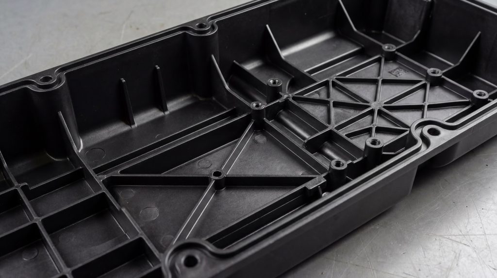
Ribs support walls, guide assembly, or resist bending; bosses commonly locate fasteners or mating parts. Their function should be stated before their geometry is changed. Review the base of each feature, nearby exterior appearance surface, flow path, ejection access, and the steel condition required to form it. A rib or boss that looks simple in the part model may create a deep pocket, a fragile steel feature, or a local mass concentration in the mold.
Provide fastener details, assembly loads, torque requirements if applicable, and the mating-part model. Ask whether the boss needs a gusset, whether the core pin is supported and serviceable, and how the feature will be inspected. Approval evidence should include the final section geometry and trial checks for appearance, assembly, and the relevant dimensions.
5. Approve the gate as a part feature, not only a tool detail
The gate is the final entrance through which resin reaches the cavity. Its position can affect the fill path, weld-line location, packing, orientation, appearance, and trimming operation. Mark areas where a gate witness is allowed and areas where it would interfere with sealing, assembly, labeling, or touch surfaces.
Ask the supplier to show the proposed gate on the current model, name the removal method, and identify the expected witness. If alternatives are plausible, request a comparison tied to a real decision. The gate-types and placement guide explains the specialist review. Gate approval should be closed on molded trial parts, not merely on a tool sketch.
6. Record shrinkage assumptions without turning them into guarantees
Mold shrinkage is not a single property of a polymer family. It can vary with the exact grade, reinforcement, flow direction, local geometry, packing, cooling, and measurement timing. Provide the supplier’s grade data and identify dimensions that are sensitive to directional behavior. Ask which scale or local compensation assumptions are being used and how adjustment will be handled after the first trial.
The drawing should define the part requirement; the tool team should document the engineering assumption; the trial report should show actual measured results. Equipment or process capability is not the same as a blanket finished-part tolerance. If steel-safe adjustment is proposed, record which surfaces can be changed and which dimensions the change may affect.
7. Close the pre-DFM checklist with named decisions
A useful release meeting ends with more than “DFM approved.” List every open issue, owner, affected revision, and closure evidence. If a feature blocks straight release, consult the undercut options guide. Formal DFM begins after project confirmation and addresses the actual part, material, tool, inspection needs, and trial plan.
| Review item | Question to close | Owner | Acceptable evidence |
|---|---|---|---|
| Wall transitions | Can the selected grade fill and cool the proposed sections? | Part designer and mold engineer | Section review, stated analysis inputs, and trial observation |
| Draft | Will the surfaces release with the specified finish? | Part designer and tool designer | Draft analysis and approved exceptions |
| Ribs and bosses | Are function, appearance, and tool access compatible? | Product and tooling teams | Approved section views and assembly checks |
| Gate | Are location, witness, and trimming acceptable? | Mold engineer and product owner | Marked model and trial-part approval |
| Dimensions | How will each CTQ be measured and dispositioned? | Quality and customer | Inspection plan and trial report |
FAQ
Is this checklist the same as a formal DFM report?
No. It prepares complete inputs and decision criteria. Formal DFM is the project-specific engineering review performed after the project starts.
Can we release tooling with only a polymer family such as ABS?
That leaves important behavior undefined. Provide the exact grade or a controlled candidate list and record who will approve the final choice.
Should every wall have the same thickness?
Uniformity can simplify flow and cooling, but function may require transitions. Review each transition with the grade, geometry, gate, tool, and validation plan.
Who approves the gate location?
The mold team proposes it, while the product owner must approve its effect on appearance, function, trimming, and assembly. Trial parts provide the closing evidence.
What should happen when a DFM issue remains open?
Keep it visible with an owner, affected revision, decision deadline, and required evidence. Do not silently convert an assumption into approval.
Next step: prepare the package for a project review.
Send the controlled model and drawing, grade information, cosmetic map, CTQ list, mating data, and open decisions. New designers can first read the beginner molding-design guide; complex tools belong in the advanced DFM trade-off review. Our engineers prepare the formal review once the project is confirmed. To discuss a review-ready package, contact WOKE Molds.
Planning a part like this? See our plastic injection molding service, or send your drawing for a free DFM review.