
Injection Molding Basics: An Introduction to Designing Molded Parts
Injection molding makes a part by filling a mold, cooling the material, opening the tool, and ejecting the part. A beginner need not design the mold, but the part model must allow those steps. This guide defines the basic terms and follows the review from CAD model to trial approval.
Start with the four stages of the molding cycle
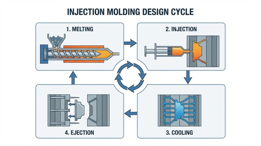
First, the machine closes the mold. Second, plastic enters the cavity through a runner and gate. Third, the material is held and cooled until the part can keep its shape. Fourth, the mold opens and the ejection system pushes the part out. Every feature in the CAD model affects at least one of these stages.
At the first review, mark the part’s function, mating surfaces, visible faces, and important dimensions. Identify the intended material by exact supplier grade if possible. A broad name such as PP or ABS describes a material family, not one fixed set of flow, shrinkage, or strength values.
| Basic term | Plain-language meaning | What to mark on the model | What the review decides |
|---|---|---|---|
| Parting line | Where mold sections meet around the part | Visible and sealing surfaces | Whether the proposed witness location is acceptable |
| Draft | A taper that helps a surface leave the mold | Opening direction and vertical faces | Which faces need taper or a documented exception |
| Gate | The final entrance for plastic into the cavity | Allowed mark and trim zones | Where entry and gate witness may be placed |
| Ejector | A tool feature that pushes the cooled part out | Faces that can accept contact marks | How the part will be supported during release |
| CTQ | A feature critical to fit, function, or safety | Datum and functional interface | How it will be measured and accepted |
Understand core, cavity, and parting line
A simple mold has two main halves. The core commonly forms internal features, and the cavity commonly forms the outside shape. When the mold opens, the part is usually kept on the side equipped for ejection. The line where tool sections meet can leave a visible witness called the parting line.
These names do not decide the tool. The mold designer considers appearance, part retention, machining access, ejection, and feature shape. Review the proposed opening direction and parting line on the actual model.
Use draft to help the part release
Draft is a slight taper on a surface that would otherwise rub against the mold as the part is ejected. Without suitable release geometry, the part may drag, show marks, deform, or require more ejection force. The needed draft depends on the exact surface, depth, finish, texture, resin, and tool movement.
Begin by choosing a likely mold-opening direction and running a draft check on faces aligned with it. Mark textured faces and surfaces whose size cannot change freely. The draft-angle guide explains the main variables. The final value still belongs in the project DFM and must be checked on trial parts.
Review walls, corners, ribs, and bosses together
A wall is the main shell of the part. Large thickness changes can create different filling, packing, and cooling behavior in nearby regions. A corner connects surfaces; a gradual transition can reduce an abrupt change in flow or stress, but it does not automatically solve every defect. A rib is a thin supporting feature, while a boss is usually a raised cylindrical feature used for locating or fastening.
Do not copy one thickness or rib ratio into every design. Review the exact material grade, flow path, function, local geometry, and tool temperature control. At each rib or boss, inspect the intersection with the main wall and the opposite visible surface. Provide the mating component and fastener information so the supplier understands why the feature exists.
Learn what gates, cooling, and ejection do
The gate is the last restricted passage before plastic enters the part cavity. Its location influences how the cavity fills and where a gate witness remains after separation. The runner carries material toward the gate. Some tools use cold runners; others use heated runner components. Beginners should focus first on the entry location, allowed mark, trim method, and protected functional areas. The gate design guide covers the focused comparison.
Cooling passages carry temperature-control fluid through the tool. Actual cooling depends on the part, resin, tool geometry, circuit, and process. The practical mold cooling overview explains what to ask. Ejector components then push the part from the tool; their contact locations should support release without unacceptable marks.
Recognize an undercut before the mold is designed
An undercut is a feature that blocks straight removal in the chosen opening direction. A side hole, hook, or clip may be an undercut. The design may be changed, or the mold may use a moving component such as a slide or lifter. At beginner level, the key step is to identify the blocked direction and ask whether the feature is essential.
Do not choose a mechanism from a short checklist. Mark the feature, its function, and the allowed witness area, then let the mold team compare options. The undercut options guide provides more detail when the basic review finds one.
Follow a simple design-review workflow
Begin with a concept review before the drawing is crowded with dimensions. Confirm the material candidates, opening direction, visible surfaces, assembly interfaces, and critical functions. Next, send a controlled model and drawing for formal DFM after the project starts. The supplier should return marked views, questions, proposed tool choices, and open issues.
Resolve the open issues before tool release. After the mold is built, use trial parts to check appearance, assembly, important dimensions, gate witness, ejection marks, and any expected movement. Record the actual resin grade, cavity, machine, process revision, measurement method, and result. The molding CTQ guide helps define important dimensions without confusing equipment capability with a finished-part tolerance guarantee.
| Review stage | What you provide | What the mold team returns | Decision to record |
|---|---|---|---|
| Concept | Part purpose, material candidates, mating parts, visible faces | Early concerns and missing inputs | Whether geometry is ready for detailed review |
| Formal DFM | Controlled model, drawing, exact grade or candidates, CTQs | Parting, draft, gate, ejection, undercut, and tooling proposal | Approved changes and remaining owners |
| Tool release | Approved part revision and acceptance needs | Released tool design and validation plan | Authority to manufacture the tool |
| Mold trial | Agreed material and inspection requirements | Parts, process record, measurements, and issue list | Correction, further trial, deviation, or approval |
| Production handoff | Approved samples and controlled requirements | Process and maintenance records | Released production basis and change control |
Know what a drawing should and should not promise
A useful drawing defines datums, dimensions, material, finish, appearance zones, and functional notes. It should not assume that one tolerance applies equally to every molded feature. Ask how and when each important dimension will be measured and which function it supports.
If a requirement is uncertain, mark it for review instead of inventing a value. The mold team may propose an adjustment strategy, but the customer owns functional acceptance. Engineering capability, machine specification, and finished-part acceptance are different statements.
FAQ
What is the first thing to check in a molded-part model?
Identify the likely mold-opening direction, visible surfaces, assembly interfaces, material candidates, and features that could block release.
Does every vertical wall need the same draft?
No. Depth, texture, finish, material, release direction, and tool action differ. Review each relevant face in the actual model.
Is a gate mark always hidden?
No. The location and style determine where the witness appears. Mark acceptable and prohibited zones before approving the gate.
What is the difference between a rib and a boss?
A rib is usually a supporting wall-like feature. A boss is commonly a raised feature used for a fastener or locator. Both need review at their connection to the main wall.
When is the design finally approved?
Part geometry can be released for tooling after DFM issues are closed, but the molded result still needs trial evidence and the agreed inspection or functional approval.

Next step: bring a clear beginner package to the mold team.
Bring the controlled model and drawing, material candidates, mating information, visible-surface map, CTQs, and open questions. Next, use the pre-DFM release checklist; complex tooling decisions are explained in the advanced DFM review. Our engineers prepare a formal review after project confirmation. To discuss the next step, contact WOKE Molds.
For production support, explore our plastic injection molding service. You can also share your drawing for an engineering review.