
Injection Molding Lifter: Angle, Clearance and Wear
An injection molding lifter is a mold component that releases internal undercuts by moving at an angle as the part is ejected. It is used where a side slide cannot reach, such as clips, hooks and snap features on the inside of a housing. Lifters are compact and effective, but they are also one of the most common sources of drag marks, sticking and wear in a mold.
Most lifter problems start in design, not in production. For example, a lifter angle that is too steep for the travel can bind after a few thousand shots. Likewise, a lifter that rubs a textured wall can scratch every part. In this guide, we explain how an injection molding lifter works, how to set its angle and travel, which clearances matter and what to check for wear. For undercut design in general, see our guide to undercuts in molded parts.
An injection molding lifter is an angled core that moves with the ejector plate. As the plate moves forward, the lifter travels up and sideways at the same time, pulling the molding face away from an internal undercut. Its sideways travel equals the ejector stroke times the tangent of the lifter angle. Typical angles are about 3–12°, with the travel set at least 2–3 mm more than the undercut depth. Key checks are clearance in the guide, a hardened or coated sliding surface, cooling where possible and room for the part to clear the lifter head.
In short: size the lifter angle from the undercut depth and ejector stroke, and design the guides and surfaces for wear from the start.
Key points:
- Travel: sideways travel = ejector stroke × tan(angle).
- Angle: small angles reduce wear but need longer strokes.
- Wear: guides, coatings and lubrication decide lifter life.
What Is an Injection Molding Lifter?
An injection molding lifter is a moving core mounted at an angle in the core side of the mold. It forms part of the molding surface, usually an internal undercut, and releases it during ejection.
A lifter assembly typically includes:
- Lifter head, which forms the undercut
- Lifter rod or blade, set at the lifter angle
- Guide bushing or wear plate in the core insert
- Slider base on the ejector plate, allowing the sideways movement
- Return mechanism, usually the ejector plate itself
Lifters are a standard feature in complex molds. Our injection mold manufacturing work regularly includes complex slide and lifter structures.
Key Takeaway: Treat the lifter as a moving part with a service life, not as a fixed core.
When Do You Need a Lifter Instead of a Slide?
You need an injection molding lifter instead of a slide when the undercut is on the inside of the part, where a slide cannot reach from the mold side.
| Feature | Lifter | Side slide |
|---|---|---|
| Undercut location | Inside the part | Outside wall |
| Actuation | Ejector plate | Angle pin, cam or cylinder |
| Typical travel | Small, a few millimeters | Larger travel possible |
| Space needed | Inside the core | Outside the cavity |
| Main risk | Wear and drag marks | Flash and slide lock wear |
For example, an internal clip on a battery cover usually needs a lifter. An external side hole usually needs a slide. Our guide to side action injection molding covers slides in detail.
Key Takeaway: If a part redesign can remove an internal undercut, it is often cheaper than a lifter.
How Do You Calculate Injection Molding Lifter Angle and Travel?
You calculate injection molding lifter angle and travel from the undercut depth and the available ejector stroke.
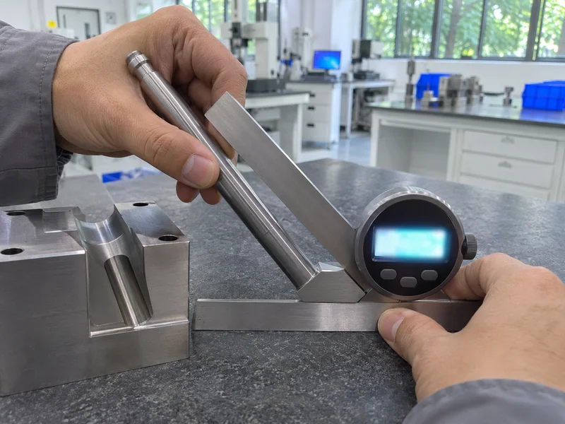
Sideways travel = ejector stroke × tan(lifter angle)
A worked example:
- Undercut depth: 3 mm
- Required travel: 3 mm + 2 mm clearance = 5 mm
- Available ejector stroke: 40 mm
- Required angle: tan⁻¹(5 ÷ 40) ≈ 7.1°
Practical rules:
- Keep the angle moderate. About 3–12° is common; steeper angles raise side load and wear.
- Add clearance. The travel should exceed the undercut by about 2–3 mm, so the part clears the head.
- Check the part. The part must not move sideways with the lifter, or it can be dragged.
Key Takeaway: If the required angle is steep, increase the ejector stroke or reduce the undercut depth.
What Clearances Does an Injection Molding Lifter Need?
An injection molding lifter needs controlled clearances so it slides freely without flashing or wobbling.
Check these clearances:
- Molding face shutoff: tight enough to prevent flash, according to the resin’s flash tendency.
- Guide fit: a sliding fit with room for heat expansion and lubrication.
- Back clearance: the space behind the lifter head must allow full travel.
- Neighbor features: ribs and bosses must not block the lifter path.
- Part clearance: the part must lift off the head without catching.
For example, a lifter in a PP part needs a tighter shutoff than one in a PC part, because PP flashes more easily. Our guide to parting line injection molding explains shutoff and flash control.
Key Takeaway: Check the full lifter path in 3D with the ejector plate moving. A static model hides collisions.
How Do You Prevent Drag Marks and Sticking?
You prevent drag marks and sticking on an injection molding lifter by giving the part enough draft, keeping surfaces smooth and controlling the release sequence.
Common fixes:
- Draft on the lifter head, so the part separates cleanly
- Polish or coat the sliding faces, such as with nitriding or DLC
- Avoid textured walls next to the lifter path, or add extra draft there
- Cool the lifter when it forms a large area, to reduce sticking
- Balance the ejection, so the part rises evenly
For example, a black textured housing can show white rub marks beside a lifter. Adding draft to the textured wall and polishing the lifter face usually removes them. Our guide to ejector pin marks covers related ejection marks.
Key Takeaway: Most lifter marks are draft and finish problems. Fix them in the design review.
How Do You Check an Injection Molding Lifter for Wear?
You check an injection molding lifter for wear by inspecting its sliding faces, guide fit and molding edge at planned intervals.
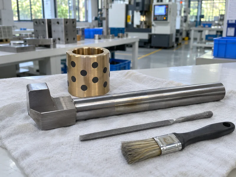
Wear checks include:
- Galling or scoring on the lifter rod and guide
- Flash at the lifter shutoff
- Play in the guide, felt by hand when the mold is open
- Burrs or rounding on the molding edge
- Lubrication condition and cleanliness
For example, flash that grows at one lifter, but not at the others, usually points to guide wear. Replacing the wear plate early is cheaper than re-cutting the core. Our guide to mold maintenance lists preventive checks.
Key Takeaway: Record lifter wear and flash at each maintenance. Trends show when to replace parts.
What Materials and Coatings Work for Lifters?
Lifters work best in hardened tool steels with wear-resistant surfaces, sliding against a different material or coating to avoid galling.
Common choices:
- Lifter body: hardened tool steel, such as 1.2344 / H13 or similar
- Guide or wear plate: bronze with graphite plugs, or hardened steel with a different hardness
- Surface treatment: nitriding, DLC or PVD for sliding faces
- Lubrication: high-temperature mold grease, applied in service
Mold steels and treatments are chosen per resin and mold life. Steel properties are documented in standards such as those from ASTM International, and our guide to injection mold components explains how lifters fit into the mold structure.
Key Takeaway: Avoid steel-on-steel of the same hardness in the guide. A bronze or coated pair lasts longer.
FAQ
- Q: What is a lifter in injection molding?
- It is an angled core that moves with the ejector plate to release an internal undercut during ejection.
- Q: How do you calculate lifter travel?
- Sideways travel equals the ejector stroke multiplied by the tangent of the lifter angle.
- Q: What is a typical lifter angle?
- About 3–12°. Smaller angles reduce wear but need a longer ejector stroke.
- Q: What is the difference between a lifter and a slide?
- A lifter releases internal undercuts using the ejector plate; a slide releases external undercuts using an angle pin, cam or cylinder.
- Q: Why do lifters cause drag marks?
- Usually because of low draft, rough or textured surfaces, or uneven ejection.
Conclusion
An injection molding lifter releases internal undercuts, but it only works reliably when its angle, travel, clearances and wear surfaces are designed together. Calculate the travel, check the path in 3D and plan for maintenance. To review undercuts and lifters on your part, send your 3D model and 2D drawing to our engineers.