
Side Action Injection Molding: Slides, Travel, Shutoffs
Side action injection molding uses moving mold components, called side actions, slides or lifters, to form features that cannot be released in the mold’s opening direction. Holes in side walls, snap hooks, external threads and side windows are typical examples. The side action moves out of the way before the part is ejected, then returns before the next shot.
Side actions solve design problems, but each one adds mold cost, lead time and maintenance. For example, a housing with four side holes may need four slides, or only one if the holes are aligned on the same face. In this guide, we explain how side actions work, how to design slide travel and shutoffs, how to plan maintenance access and when to redesign the part instead. For the broader topic, see our guide to undercuts in molded parts.
Side action injection molding uses mechanisms that move at an angle to the mold opening direction to form undercuts. Common types are cam-driven slides (angle pins or cams pull the slide sideways as the mold opens), hydraulic core pulls (cylinders move the core independently) and lifters (angled cores that move with the ejector system to release internal undercuts). Key design points are enough slide travel to clear the undercut, robust shutoffs with draft, locking against injection pressure, cooling and maintenance access.
In short: side actions make undercuts possible, but every slide adds cost, so use them only where the part needs them.
Key points:
- Types: angle-pin slides, hydraulic core pulls and lifters.
- Design: travel, shutoff angle, locking and cooling decide reliability.
- Cost: each side action adds mold cost and maintenance.
What Is Side Action Injection Molding?
Side action injection molding is molding with a mold that has one or more parts moving sideways, in addition to the main opening movement. The side action forms an undercut, then moves away so the part can be ejected.
Typical features that need side actions:
- Holes or slots in side walls
- Snap hooks and latches facing sideways
- External threads on some parts
- Side windows and openings
- Textured side walls with no draft in the opening direction
Without side actions, these features would lock the part in the mold. Our guide to parting line injection molding explains how the opening direction defines what counts as an undercut.
Key Takeaway: Any feature that blocks straight opening needs a side action, a lifter or a redesign.
What Types of Side Actions Are Used in Side Action Injection Molding?
In side action injection molding, the types of side actions differ in how they are driven and what they release.
| Side action type | How it moves | Best for | Limits |
|---|---|---|---|
| Angle-pin slide | Angled pin pulls slide as mold opens | External undercuts, side holes | Travel limited by pin angle and length |
| Cam or dog-leg slide | Cam delays slide movement | Slides that must move later in the stroke | More complex |
| Hydraulic core pull | Cylinder moves the core | Long travel, timing control | Higher cost, hydraulic connections |
| Lifter | Angled core moves with ejector plate | Internal undercuts, small snap hooks | Limited travel, wear |
| Collapsible core | Core collapses inward | Internal threads and rings | Specialized, higher cost |
For threads, unscrewing molds are another option. See our guide to unscrewing injection mold design.
Key Takeaway: Match the side action type to the undercut depth and position. Long travel often means hydraulic core pulls.
How Much Travel Does a Side Action Need?
In side action injection molding, a slide needs enough travel to clear the undercut completely, plus a safety margin. If the slide does not move far enough, the part drags or breaks during ejection.
For an angle-pin slide, travel depends on the pin angle and the opening stroke over the pin:
Slide travel ≈ effective pin length × sin(pin angle)
Practical rules:
- Margin: design travel a few millimeters beyond the undercut depth.
- Pin angle: angles are usually kept moderate, often around 15–25°, to limit force and wear.
- Longer travel: use cams or hydraulic cylinders when angle pins become too long.
- Retention: springs, ball detents or stops hold the slide in its open position.
For example, a 6 mm deep side hole may need around 8–10 mm of slide travel. An angle pin that cannot provide that within the mold height may need to be replaced by a hydraulic core pull.
Key Takeaway: Check slide travel against the deepest point of the undercut, not its average depth.
How Should Side Action Shutoffs Be Designed?
In side action injection molding, shutoffs should be designed with draft, enough contact area and firm locking, so plastic cannot flash between the slide and the mold.
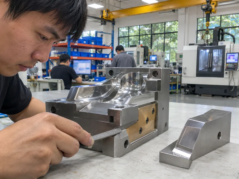
Good shutoff practice:
- Angled shutoffs: add a few degrees of angle so surfaces do not rub during movement.
- Heel blocks or wedge locks: hold the slide against injection pressure.
- Hardened wear plates: protect sliding surfaces.
- Avoid knife edges: thin steel edges break and flash.
- Venting: let air escape where the slide meets the cavity.
For example, a slide that relies only on the angle pin for locking can be pushed back by injection pressure, which causes flash on every shot. A wedge lock that pre-loads the slide prevents this. Our guide to injection mold venting explains why slide areas need vents.
Key Takeaway: In side action injection molding, ask how each slide is locked. Locking, not the angle pin, holds the slide during injection.
How Do Side Actions Affect Part Appearance?
In side action injection molding, slides affect part appearance because every slide adds its own parting lines on the part. These lines can show as fine witness lines, small steps or flash.
To control appearance:
- Place slide parting lines on edges or hidden faces.
- Align slide boundaries with design features, such as grooves.
- Specify where witness lines are acceptable on the drawing.
- Keep shutoffs maintained to prevent flash over time.
Textured side walls are another case. Texture on a wall parallel to the opening direction needs extra draft, or a slide, so it does not scuff. Our guide to injection molding surface finishes explains texture draft requirements.
Key Takeaway: Mark cosmetic surfaces before mold design, so slide lines can be placed elsewhere.
How Do You Plan Maintenance Access for Side Actions?
You plan maintenance access for side actions by designing them so they can be inspected, cleaned and replaced without taking the whole mold apart. Slides are among the highest-wear parts of a mold.
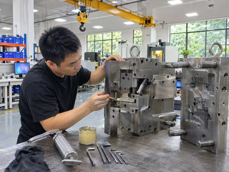
Maintenance-friendly design includes:
- Removable wear plates and gibs
- Slides that can be removed from the parting line where possible
- Grease points that are reachable in the press
- Replaceable inserts for features that wear or break
- Spare parts for angle pins, springs and wear plates, preferably standard components to ISO or supplier catalog standards
For example, a slide whose angle pin can only be reached after removing the clamp plate can turn a one-hour repair into a full day. Our article on mold maintenance explains typical inspection intervals.
Key Takeaway: Ask how a slide is removed and serviced during the design review. Downtime costs more than steel.
When Should You Avoid Side Action Injection Molding?
You should avoid side action injection molding when a simple design change can remove the undercut. Fewer side actions mean lower mold cost, shorter lead time and less maintenance.
Common design alternatives:
- Pass-through cores: form a snap hook with a hole through the part, using the main core and cavity.
- Moving holes to faces parallel to the opening direction
- Bump-offs: small, flexible undercuts that can strip off during ejection, in suitable materials
- Splitting the part into two simpler parts
- Post-molding drilling, for very low volumes
For example, a side snap hook can often be molded with a pass-through window, removing a slide entirely. Our engineering and DFM review checks each undercut for these options.
Key Takeaway: Review every undercut at DFM. Removing one slide can save significant mold cost.
How Do Side Actions Change Mold Cost and Lead Time?
In side action injection molding, slides change mold cost and lead time because each one adds design, machining, fitting and testing work. Multi-cavity molds multiply this, because each cavity may need its own slides.
Cost drivers include:
- Number of side actions per cavity
- Type: angle-pin slides cost less than hydraulic pulls or collapsible cores
- Travel and size of each slide
- Cooling inside the slide
- Precision of shutoffs
As a result, the number and type of side actions are among the first things to compare between mold quotes. Complex slide and lifter structures are part of our regular mold scope; see our injection mold manufacturing page.
Key Takeaway: Ask each supplier to list side actions per cavity in the quote. It explains most price differences.
FAQ
- Q: What is a side action in injection molding?
- It is a moving mold component, such as a slide or lifter, that forms an undercut and moves away before the part is ejected.
- Q: What is the difference between a slide and a lifter?
- A slide moves sideways, usually driven by an angle pin or cylinder, for external undercuts. A lifter moves at an angle with the ejector plate, usually for internal undercuts.
- Q: How much travel does a slide need?
- Enough to clear the deepest point of the undercut plus a safety margin of a few millimeters.
- Q: Why do side actions cause flash?
- Flash forms when the slide is not locked firmly, when shutoffs wear, or when shutoff surfaces are poorly fitted.
- Q: How can I avoid side actions?
- Use pass-through cores, move holes to faces parallel to the opening direction, use bump-offs or split the part.
Conclusion
Side action injection molding makes undercuts possible, but every slide adds cost, lead time and maintenance. Design enough travel, firm locking and good access, and remove undercuts that a design change can avoid. To review the undercuts in your part, send your 3D model and 2D drawing to our mold engineers.