
Unscrewing Injection Mold Design: How to Get the Best Fit
Unscrewing injection mold design is the right choice when a molded thread must keep its full profile and cannot be stripped or collapsed off the core. In this design, a motor or a hydraulic rack turns each threaded core, so the part unscrews itself while it is held still. However, the drive, the core return and the ejection sequence add risk, so these details decide whether the mold runs for years or stalls in production.
Many buyers only discover this after the first mold trial. For example, a cap that turns with the core, or a core that does not return to the same start position, quickly turns a good part design into scrap and downtime. In this guide, we explain the choices we review when we build unscrewing injection molds for threaded parts.
Unscrewing injection mold design uses rotating threaded cores, driven by a rack, gear train, hydraulic motor or servo motor, to release internal or external threads without damaging them. It suits high-volume parts with full, accurate threads, such as caps, closures and fittings. The critical design points are part anti-rotation, the number of core turns, core retention on the return stroke, drive position confirmation and the interlock between core backoff and ejection.
In short: the thread decides the release method, and the sequence decides whether the mold runs reliably.
Key points:
- Use unscrewing when the thread must be complete, accurate and repeatable over high volumes.
- Lock the part against rotation with ribs, teeth or knurls, or the core will simply spin the part.
- Confirm every movement with sensors and interlocks, so the mold never closes or ejects on a core in the wrong position.
What Is Unscrewing Injection Mold Design and When Is It Needed?
Unscrewing injection mold design is a tooling approach where threaded cores rotate out of the molded part after it cools. As a result, the thread forms completely, with no stripping marks and no split lines across the thread.
You need it when other release methods damage the thread or the function. For instance, a stripped thread works only with flexible materials and shallow thread depth. A collapsible core works for some internal threads, but its segments leave witness lines and limit the diameter range.
Unscrewing is usually needed when:
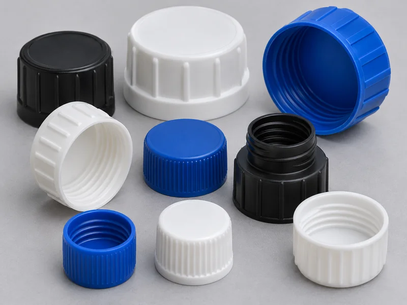
- The thread is deep, steep or made in a stiff material such as PC, POM, PA66 GF or PBT.
- The thread must seal, such as on a cap, a valve body or a fluid fitting.
- Volumes are high, so a fast automatic cycle pays back the extra tooling cost.
- The thread is full-circle, with no flats or interruptions allowed.
On the other hand, unscrewing is not the best answer for every threaded part. Low-volume parts, short threads in soft materials, or threads with flats can often use simpler tooling, such as hand-loaded inserts or side actions.
Key Takeaway: Choose unscrewing injection mold design when thread quality and volume justify it. For short, soft or low-volume threads, a simpler release method usually costs less.
Which Thread Release Method Fits Your Part?
The right thread release method depends on thread depth, material stiffness, part volume and cosmetic needs. Therefore, it helps to compare the four common options side by side before the mold design starts.
| Release method | How it works | Best for | Main limits |
|---|---|---|---|
| Unscrewing cores | Cores rotate out of the part | Full, accurate threads at high volume | Higher tooling cost, drive and sensors needed |
| Collapsible core | Core segments collapse inward | Internal threads and undercuts in larger diameters | Witness lines, diameter and stroke limits |
| Stripping (bump-off) | Part is pushed off a fixed core | Shallow threads in flexible materials such as PP or PE | Not suitable for stiff or glass-filled resins |
| Side actions / split cavity | Slides form the thread from outside | External threads where a parting line is acceptable | Parting line across the thread |
For example, a polypropylene closure with a shallow thread can often be stripped. A glass-filled nylon fitting with a sealing thread, by contrast, needs unscrewing, because stripping would shear the thread.
In practice, the decision also depends on the cavity count. A 2-cavity prototype mold might use loose threaded inserts that an operator unscrews. A 16-cavity production mold, however, needs an automatic drive to hold a steady cycle.
Key Takeaway: Match the release method to the thread and the volume. If the resin is stiff or the thread must seal, plan for unscrewing injection mold design from the start.
How Do Drive Systems Work in Unscrewing Injection Mold Design?
Drive systems in unscrewing injection mold design turn every threaded core the same number of turns, at the same time, with enough torque to break the part free. The drive choice affects mold size, cost, cycle time and maintenance.
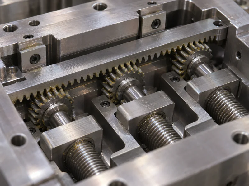
Rack and pinion drives
A hydraulic cylinder pushes a toothed rack, and the rack turns a pinion on each core or on a central gear:
- Simple, robust and common for 1 to 8 cavities.
- The rack length grows with the number of turns, so long threads need gearing.
- The rack stroke must be checked against the mold size and the machine’s space.
Hydraulic or electric motor drives
A motor turns a central gear, and a gear train drives every core:
- Suits many cavities and threads that need many turns.
- A servo motor gives programmable speed, torque and position.
- It needs a controller and a clean interface with the molding machine.
Mechanical drives from the mold opening
Some designs use the opening stroke and a lead screw to turn the cores:
- No separate power source is needed.
- However, the opening stroke limits the number of turns.
- Timing is tied to the machine’s opening speed, which reduces flexibility.
The number of turns is the key input. For example, a thread length of 10 mm with a 2 mm pitch needs 5 turns, plus extra rotation for clearance. Every added turn adds drive length or cycle time, so we always check the turn count before choosing the drive.
Key Takeaway: Count the core turns first, then choose the drive. Rack drives suit short threads and few cavities; motor drives suit many cavities and long threads.
How Do Thread Geometry and Anti-Rotation Affect Unscrewing Injection Mold Design?
Thread geometry and anti-rotation features decide whether the part comes off the core or simply spins with it. In unscrewing injection mold design, the part must be held still while the core turns.
Features that stop the part from turning
The part needs a feature that the cavity or stripper plate can grip:
- External ribs, knurls or teeth on a cap skirt
- Flats or hex shapes on a fitting body
- Small anti-rotation teeth on the part face that engage the stripper ring
Thread details to check before tooling
- Pitch and thread length, which set the number of turns
- Thread start and run-out, which affect where the core stops
- Wall thickness around the thread, which affects shrinkage onto the core
- Thread tolerance, especially for sealing threads and mating parts
Here’s the thing: many part designers add a smooth skirt for appearance, then the mold has nothing to hold. As a result, the first trial shows parts turning with the cores. Adding ribs late means changing both the part and the cavity steel.
Key Takeaway: Design the anti-rotation feature together with the thread. It is far cheaper to add ribs in the part model than to modify hardened cavity steel after T1.
How Does Unscrewing Injection Mold Design Retain the Core on the Return Stroke?
The unscrewing core is retained during the return stroke by a guided thread nut or lead screw, plus a positive stop at its home position. Without this, the core can drift, overrun or stop at the wrong angle, and the next shot forms a damaged thread.
During unscrewing, each core backs out along a lead thread that matches the part thread pitch. Then, on the return stroke, the drive turns the core back in to its molding position. The core must reach the same axial and angular position every cycle.
Good retention design includes:
- A hardened lead nut with the same pitch as the molded thread, so the core moves axially in step.
- A positive end stop, so the core cannot over-travel when the drive pushes it home.
- Clearances that allow thermal growth, so the core does not bind when the mold heats up.
- Lubrication access for the lead thread and gears.
Return-stroke problems often show up only after the mold reaches full temperature. That is why trials should run at production mold temperature, not only at a cold start.
Key Takeaway: Treat the return stroke as carefully as the unscrewing stroke. A core that returns to a slightly different position each cycle will slowly ruin thread quality.
How Does the Mold Confirm Drive Position Before Closing?
The mold confirms drive position with sensors that report each end position to the molding machine before it is allowed to close or inject. In unscrewing injection mold design, this is the main protection against crashed cores.
Typical position confirmation uses:
- Limit switches at the rack or cylinder end positions
- Proximity sensors on a gear, a cam or the rack
- Encoder feedback on servo motor drives
- Core-in signals wired to the machine’s mold-close permission
The machine–mold interface should follow the signal and connection conventions agreed with the molder. For example, many European molders use EUROMAP interface standards for machine and mold connections, so the mold drawing should state which interface the press uses.
However, a sensor only helps if it checks the right thing. A switch on the cylinder confirms the cylinder position, not the actual core position. If a gear tooth slips, the cylinder can be home while a core is not. Therefore, high-risk molds often check the gear or core position directly.
Key Takeaway: Confirm core position, not just cylinder position. Ask your mold maker which signal proves the cores are home before the mold closes.
How Should Core Backoff and Ejection Be Interlocked?
Core backoff and ejection should be interlocked so that ejection can only start after the cores have fully unscrewed, and the cores can only return after the part has cleared. If the order is wrong, the ejector pushes a part that is still threaded onto the core.
A typical safe sequence is:
- Mold opens to the unscrewing position.
- Cores unscrew while the part is held by the anti-rotation feature.
- The drive confirms the full backoff position.
- The stripper plate or ejectors push the part off.
- Ejection returns and is confirmed.
- Cores return to the molding position and are confirmed.
- The mold closes for the next shot.
In some designs, the stripper plate advances in step with the core during unscrewing. This keeps pressure on the part face, so it releases cleanly. However, the timing between the core pitch and the plate stroke must be exact.
A good mold trial report records the sequence settings and the sensor signals used. As a result, the molder can rebuild the same sequence after a mold change, instead of guessing.
Key Takeaway: Write the sequence down and interlock every step. Most unscrewing mold crashes come from a step that ran too early, not from a weak part.
How Do Cavities, Cooling and Cycle Time Change in Unscrewing Molds?
Cavities, cooling and cycle time all change because rotating cores are harder to cool and every turn adds time. Therefore, unscrewing injection mold design needs an early cycle-time estimate, not only a cavity count.
| Design factor | Effect on the mold | Effect on cost or cycle |
|---|---|---|
| More cavities | Larger gear train, more bearings | Higher tooling cost, lower cost per part |
| More core turns | Longer rack or faster motor | Longer unscrewing time |
| Core cooling | Bubbler or baffle through a rotating core needs rotary seals | Better cooling shortens the cycle |
| Steel and coatings | Hardened cores, wear-resistant gears | Longer mold life |
The same trade-off appears in any high-cavitation tool, as our comparison of multi-cavity and family injection molds explains.
Cooling deserves special attention. A threaded core that runs hot holds the part longer, so the cycle grows. In addition, uneven core temperature changes shrinkage, which changes the thread fit. A cooling review, and a mold flow analysis when the project needs one, helps balance cavities before steel is cut.
Key Takeaway: Plan cooling and turn count together with the cavity count. A cheaper 8-cavity layout can lose to a well-cooled 4-cavity mold on output per hour.
What Should Buyers Send to Quote an Unscrewing Injection Mold Design?
Buyers should send a 3D model and a 2D drawing with thread callouts, tolerances and material. With these, a mold maker can count turns, check anti-rotation and propose a drive.
A useful quote package includes:
- 3D part model (STEP preferred) and 2D drawing with the thread standard and class
- Resin grade, including any glass fiber or flame retardant
- Annual volume and target cavity count
- Molding machine details, such as tonnage, core-pull hydraulics and interface
- Thread function, for example sealing, torque or child-resistant use
At WOKE Molds, a typical mold lead time is 4–8 weeks, depending on complexity, steel, hot runner and validation. Our standard mold quote includes up to 3 mold trials and 10-shot samples. Formal DFM starts after project kickoff, and Moldflow is applied when the project complexity calls for it. You can also review our custom injection mold manufacturing process and our guide to molded threads and how to design them.
Key Takeaway: Give the mold maker the thread function and the volume, not only the geometry. Those two inputs decide the drive, the cavity count and the price.
FAQ
- Q: What is an unscrewing injection mold?
- It is a mold with threaded cores that rotate out of the part after molding. The rotation releases internal or external threads without stripping or splitting them.
- Q: When should I use a collapsible core instead of unscrewing?
- A collapsible core can suit larger internal threads or undercuts at moderate volume. Unscrewing is better when the thread must be complete, accurate and free of witness lines.
- Q: How do you stop the part from turning with the core?
- The part needs an anti-rotation feature, such as ribs, knurls, flats or small teeth. The cavity or stripper ring grips this feature while the core turns.
- Q: Are unscrewing molds more expensive?
- Yes. The drive, gears, bearings and sensors add tooling cost. At high volume, the automatic cycle usually pays this back through lower part cost.
- Q: What files do I need to quote an unscrewing mold?
- A 3D model and a 2D drawing with the thread callout, material and annual volume are enough to start. Machine details can follow.
Conclusion
Unscrewing injection mold design delivers full, accurate threads when the part has good anti-rotation features and the mold has a confirmed, interlocked sequence. Plan the turn count, drive, cooling and sensors before steel is cut. To review your threaded part, send your 3D model and 2D drawing to our engineering team.