
CNC Lathe vs CNC Mill: How to Pick the Right One, No Waste
The CNC lathe vs CNC mill choice comes down to one question: is the main geometry of your part round or prismatic? A lathe spins the workpiece against a fixed tool, so it makes diameters, bores and threads efficiently. A mill spins the tool and moves it across a fixed workpiece, so it makes flats, pockets and hole patterns. In addition, many parts need CNC milling and turning together, which makes the CNC lathe vs CNC mill decision a planning question, not just a machine question.
Picking the wrong machine rarely stops a part from being made. However, it quietly adds setups, fixtures and inspection steps. On a batch order, every extra setup adds programming, fixturing and another first-article check. In our precision CNC machining service, we see this most often on parts that sit between the two worlds: shafts with flats, housings with bores, and flanges with bolt patterns.
A CNC lathe is the better choice when most of a part’s features are concentric with one axis, such as shafts, pins, bushings and threaded fittings. A CNC mill is the better choice for flat, multi-sided or pocketed parts, such as brackets, plates and housings. Many real parts need both, so the right plan decides which machine makes the main geometry and which one adds the secondary features.
In short: start with the main geometry, not the machine you know.
Key points:
- Round main geometry (diameters, bores, threads on one axis) belongs on a CNC lathe or a mill-turn center.
- Prismatic main geometry (flats, pockets, hole patterns on several faces) belongs on a 3-axis or 5-axis CNC mill.
- Mixed parts cost less when the drawing, datums and tolerances support the fewest possible setups.
What Is the Real Difference Between a CNC Lathe vs CNC Mill?
The real difference between a CNC lathe vs CNC mill is which element rotates. On a lathe, the workpiece rotates and a stationary tool removes material. On a mill, the cutting tool rotates and the machine moves it along X, Y and Z, plus extra rotary axes on a 5-axis machine.
As a result, that single difference controls everything downstream. A rotating workpiece naturally produces surfaces that share one axis. Therefore, concentricity and roundness come almost for free on a lathe. In contrast, a rotating tool can reach any face the spindle can approach. So a mill handles pockets, slots, hole patterns and angled faces.
| Factor | CNC lathe (turning) | CNC mill (milling) |
|---|---|---|
| What rotates | Workpiece | Cutting tool |
| Typical stock | Round bar, tube, forged blanks | Plate, block, flat bar |
| Natural features | Diameters, bores, grooves, threads, tapers | Flats, pockets, slots, holes, 3D surfaces |
| Strongest geometric control | Concentricity and roundness to one axis | Position and flatness across faces |
| Typical setups for a round part | 1–2 | 2–4 |
| Typical setups for a prismatic part | Not suitable | 1–3 (fewer on 5-axis) |
Here’s the thing: the table shows tendencies, not rules. A modern lathe with live tooling can mill a flat, and a 5-axis mill can interpolate a bore. The question is which machine makes the part with fewer setups and lower risk.
Key Takeaway: Decide by what rotates best for the part. If most features share one axis, rotate the workpiece; if they sit on several faces, rotate the tool.
Which Part Geometries Belong on a CNC Lathe vs CNC Mill?
Part geometry decides the CNC lathe vs CNC mill question for most parts. First, the quickest test is to look at the part along its longest axis. If most features are circles around that axis, it is a turned part. Similarly, if most features are rectangles, holes and pockets on different faces, it is a milled part.
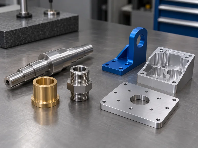
Parts that belong on a CNC lathe
These parts have a clear centerline and most tolerances reference it:
- Shafts, pins and spindles with stepped diameters
- Bushings, sleeves and spacers with an OD and ID
- Threaded fittings, nozzles and connectors
- Pulleys, rollers and round flanges without complex face features
Parts that belong on a CNC mill
These parts have flat datums and features spread across several faces:
- Brackets, plates and mounting blocks
- Housings and enclosures with internal pockets
- Manifolds with cross-drilled ports
- Fixture components and mold inserts with 3D surfaces
Parts that sit in between
These parts are where most quoting mistakes happen:
- A round flange with an off-center bolt pattern and a milled slot
- A shaft with a keyway, wrench flats and a cross hole
- A square block with a precision bore that must align with a face
For mixed parts, we usually make the main geometry first, on the machine that controls its critical tolerance. Then the secondary features follow in a second operation, or on a mill-turn center in the same clamping.
Key Takeaway: Classify the part by where its critical tolerances point. The machine that controls those tolerances makes the main geometry.
How Do Tolerances and Concentricity Differ on a CNC Lathe vs CNC Mill?
Tolerance capability differs on a CNC lathe vs CNC mill mainly in which feature relationships each machine controls naturally. A lathe holds concentricity, runout and roundness well, because every turned diameter shares the spindle axis. A mill holds position, flatness and perpendicularity well, because the machine axes are square to each other.
However, the problem starts when a part needs both kinds of control. For example, a bore that must run true to an OD is easy if both are turned in one chucking. If the OD is turned and the bore is milled in a second setup, every re-clamp adds error. As a result, a 0.02 mm runout requirement that was routine becomes a scrap risk.
ISO 2768 general tolerances on a CNC lathe vs CNC mill drawing
General tolerances also matter. For example, many drawings use ISO 2768-1 general tolerance classes for dimensions without an individual tolerance. Class m (medium) allows ±0.2 mm on a 6–30 mm dimension, while class f (fine) allows ±0.1 mm on the same range. Calling out class f across a whole part, when only three features need it, increases inspection time on every dimension.
- Use class m as the default for non-critical dimensions.
- Put individual tolerances only on functional features, such as fits and sealing faces.
- State on the drawing which edition of ISO 2768 applies.
| Requirement | Easier on | Why |
|---|---|---|
| Runout of OD to bore | CNC lathe | Both features share the spindle axis in one clamping |
| Coaxial stepped diameters | CNC lathe | Turned in one pass without re-clamping |
| Hole pattern position to datum faces | CNC mill | Linear axes locate holes directly |
| Flatness of large faces | CNC mill | Face milling covers the area in controlled passes |
| Bore perpendicular to a face | Either, in one setup | Depends on which feature is the datum |
Keep in mind that machine capability is not finished-part tolerance. For instance, our wire EDM equipment has a process capability of ±0.003 mm. Even so, finished tolerances are always controlled per drawing, by material, part size, setup and inspection method.
Key Takeaway: Group the features that share a tolerance relationship into one setup. That choice protects tolerances more than any machine upgrade.
When Should a Part Use Both CNC Turning and Milling?
A part should use both CNC turning and milling when its critical round features and its critical prismatic features cannot be made on one machine type without extra setups. This is common. For instance, shafts need keyways, flanges need bolt patterns, and valve bodies need both bores and ported faces.
There are three practical routes. Each one fits a different volume and tolerance situation.
Route 1: Turn first, then mill
This route suits most mixed parts in prototype and low-volume work:
- The lathe makes all diameters, bores and threads in one chucking.
- A mill then adds flats, slots and cross holes, using the turned OD as a datum.
- A V-block or collet fixture keeps the second setup repeatable.
Route 2: Mill-turn in one clamping
A mill-turn center with live tooling, a Y-axis and often a sub-spindle combines both operations:
- Best when runout between turned and milled features is tight.
- Best for medium and high volumes, where one-clamping cycles save handling time.
- Less suitable for very large prismatic features, which a mill cuts faster.
Route 3: Mill first, then turn
This route is less common but useful in specific cases:
- A block-shaped part that carries one precision bore or boss.
- The mill makes the faces and datums; a lathe or boring operation finishes the round feature.
- Often a 4-jaw chuck or a dedicated fixture holds the prismatic part on the lathe.
In practice, many buyers ask for “5-axis” on every complex part. That is often unnecessary. A turned shaft with two flats and one cross hole costs less on a lathe plus a simple 3-axis operation than on a 5-axis mill, which is slower at removing material around a full diameter.
Key Takeaway: Choose the route by which tolerances link turned and milled features. Tight links favor one clamping; loose links favor the cheaper two-machine route.
How Do Internal Corner Radii Change the CNC Lathe vs CNC Mill Choice?
Internal corner radii change the CNC lathe vs CNC mill choice because a mill cannot cut a sharp inside corner. A rotating end mill always leaves a radius equal to at least its own radius. So a pocket drawn with sharp internal corners forces either a smaller, slower tool or a secondary process.
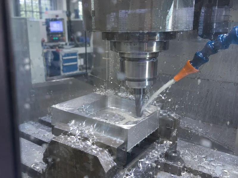
By contrast, a lathe behaves differently. Turned internal corners, such as a shoulder inside a bore, take the shape of the tool nose radius. That radius is small, often a fraction of a millimeter. Therefore, a sharp-looking shoulder on a turned part is usually cheap, while the same corner in a milled pocket is expensive.
For milled parts, a common DFM guideline is:
- Make the internal corner radius slightly larger than the tool radius, so the tool does not stall in the corner.
- Keep the corner radius at least about one third of the pocket depth where the design allows.
- Use the same radius on all corners of a pocket, so one tool finishes the whole feature.
- If a mating part needs a square corner, use a relief (dog-bone) cut instead of a sharp radius.
If a design truly needs a sharp inside corner in a pocket, sinker EDM or wire EDM can make it. But that adds an electrode, a second machine and more lead time. In our experience, the drawing often allows a radius once the buyer knows the cost difference.
Key Takeaway: Draw the largest internal radius your mating parts accept. On milled pockets, that single change often removes a secondary EDM step.
What Limits Deep Pockets and Thin Walls on a CNC Mill?
Deep pockets and thin walls are limited on a CNC mill by tool length and part rigidity. A long tool deflects and chatters, and a thin wall vibrates away from the cutter. As a result, both effects reduce accuracy, surface finish and tool life.
Deep pocket milling
The ratio between pocket depth and tool diameter drives cost:
- Depths up to about 3–4 times the tool diameter machine with standard tools.
- Deeper pockets need long-reach tools, lower feed rates and more passes.
- Very deep, narrow pockets may need EDM or a design change, such as opening the pocket from both sides.
Thin wall machining
Wall thickness and height decide whether the wall survives cutting:
- Common guidelines suggest about 0.8 mm minimum for metal walls and about 1.5 mm for plastic walls.
- Tall thin walls need finishing passes that alternate sides to balance stress.
- Plastics such as POM and PEEK need sharp tools and controlled heat to avoid distortion.
Similarly, the same limits apply on a lathe in a different form. A long, slim shaft deflects away from the tool, so it needs a tailstock or steady rest. A thin-walled sleeve can distort in a 3-jaw chuck, so soft jaws or a collet often help.
Key Takeaway: Treat depth-to-diameter and wall height-to-thickness as cost drivers. When either ratio is high, ask for a DFM review before releasing the drawing.
How Do Cost and Lead Time Compare for CNC Lathe vs CNC Mill Parts?
Cost and lead time compare for CNC lathe vs CNC mill parts mainly through setup count, cycle time and stock form, not through machine type alone. Hourly rates vary by market and machine. The bigger driver is how many times the part is clamped, programmed and inspected.
| Cost driver | Effect on turned parts | Effect on milled parts |
|---|---|---|
| Stock form | Round bar wastes little material on round parts | Block stock wastes more material on round parts |
| Setups | Often 1–2 | Often 2–4 for multi-face parts |
| Cycle time | Short for diameters and threads | Longer for pockets and 3D surfaces |
| Fixtures | Chucks and collets are standard | Custom fixtures may be needed for odd shapes |
| Inspection | Diameters and runout check quickly | Hole positions and flatness may need CMM time |
As a result, a round part made on a mill usually costs more than the same part made on a lathe. On the other hand, a prismatic part forced onto a lathe needs special fixtures and loses accuracy.
Likewise, lead time follows the same logic. Each extra setup adds programming, a first-article check and queue time on another machine. For prototypes, that can add days; in addition, for production it adds handling cost on every batch.
Key Takeaway: To lower cost in any CNC lathe vs CNC mill decision, reduce setups first. Ask your supplier which features force an extra clamping, then decide whether the tolerance there is truly needed.
Which Materials Machine Better on a CNC Lathe or a CNC Mill?
Materials machine well on both a CNC lathe and a CNC mill; the material changes speeds, tools and risks rather than the machine choice. However, some materials favor one process because of stock form or heat behavior.
- Aluminum (for example 6061 and 7075) machines fast on both. Bar stock suits turned parts; plate suits milled housings.
- Stainless steel work-hardens, so steady chip load matters. Turning keeps constant contact, which helps; deep milled pockets need care.
- Tool steel and hardened parts often need grinding or EDM after machining for final size.
- Brass and copper turn very well, which is why many fittings and connectors are turned parts.
- Titanium needs rigid setups and controlled heat on both machines.
- PEEK, POM and nylon move with heat and clamping force, so thin features distort more easily on either machine.
We machine aluminum, stainless steel, tool steel, carbon steel, copper, brass, titanium, PEEK, POM and nylon. For plastic parts, we usually discuss clamping and stress relief before quoting tight tolerances, because the material may move after unclamping.
Key Takeaway: In the CNC lathe vs CNC mill choice, let geometry choose the machine, then let material choose the tools and process limits. Flag plastic and thin-walled metal parts early.
What Should Buyers Send to Get the Right CNC Lathe vs CNC Mill Quote?
Buyers get the right CNC lathe vs CNC mill quote by sending a 3D model and a 2D drawing with clear datums and tolerances. As a result, the supplier decides the machine route from the geometry, not from a guess in the RFQ text.
A useful RFQ package contains:
- 3D model (STEP preferred) for programming and setup planning
- 2D drawing with datums, critical tolerances, thread callouts and surface finish
- Material and finish, such as anodizing, passivation or black oxide
- Quantity for prototype and expected production volume
- Inspection needs, such as FAI, a CMM report or material certificates
The real worry for most buyers is whether part 500 matches part 1. Our core facility uses a Leader CMM with a 1,200 × 1,000 × 800 mm measuring range, so we can check hole positions, flatness and runout against the drawing. Inspection reports, FAI and material certificates are supplied when the project requires them. You can read more about our quality control and inspection process.
For turned parts, see our CNC turning capabilities. For prismatic and multi-face parts, see 3-axis and 5-axis CNC milling. If you are not sure which applies, send the drawing and we will propose the route.
Key Takeaway: Send geometry, not machine preferences. A 3D model plus a toleranced 2D drawing lets the supplier choose the lowest-risk route.
FAQ
- Q: Is a CNC lathe or a CNC mill more accurate?
- Neither is more accurate in general. A lathe controls concentricity and roundness best, while a mill controls position and flatness best. Accuracy on a finished part depends on setup count, material and inspection, not on the machine type alone.
- Q: Can a CNC mill make round parts?
- Yes. A mill can interpolate bores and bosses, and a 4th or 5th axis can rotate the part. However, round parts with several diameters usually cost less and run truer on a lathe.
- Q: What is a mill-turn machine?
- A mill-turn machine is a CNC lathe with live tooling, usually a Y-axis and often a sub-spindle. It turns diameters and mills flats, slots and holes in one clamping, which helps when turned and milled features have tight positional links.
- Q: Why do milled pockets need internal corner radii?
- A rotating end mill always leaves a radius at least equal to its own radius. Sharp inside corners need smaller, slower tools or EDM, which adds cost and lead time.
- Q: What files do I need for a CNC machining quote?
- A 3D model (STEP preferred) and a 2D drawing with tolerances and datums are enough to start. Material, finish, quantity and inspection requirements can follow.
Conclusion
The CNC lathe vs CNC mill decision depends on where your part’s main geometry and critical tolerances sit. Group related features into the fewest setups, and avoid tolerances that force extra operations. To get a machining route and quote, upload your 3D model and 2D drawing and our engineers will review it.