
Understanding Injection Mold Cost for Parts and Tooling
Part design influences both injection mold construction and the recurring work needed to supply accepted parts. A change can simplify one operation while adding another, so design-to-cost means comparing alternatives against the same functional and acceptance requirements.
This guide focuses on engineering choices. The estimation guide explains program cost allocation, while the quotation guide helps compare supplier scope. None of these methods establishes a universal saving for a feature or material.
1. Protect the requirements that create value
Before removing geometry, identify what the part must do: support load, locate an assembly, seal, retain an insert, protect a surface or meet an appearance requirement. Mark the relevant datums, dimensions and visible zones on the controlled drawing.
Separate essential requirements from preferences that could change. A concealed surface might permit a different finish, but a sealing face cannot be relaxed solely because it is difficult to machine. The useful engineering question is which alternative meets the requirement with a more practical manufacturing and verification route.
Compare total project effects. Include tooling, cycle and handling, secondary work, inspection, assembly, maintenance and the effort to approve a change. A less expensive mold feature can still create a more demanding production operation.
2. Examine undercuts and release directions
An undercut can prevent a feature from releasing in the main mold-opening direction. Depending on geometry and material, the solution may involve a different parting line, a slide, a lifter, rotational release, a removable insert or a revised feature.
Each route changes more than machining. Consider support, shutoffs, travel, sequencing, access, wear, press services and the condition of the part during release. Manual handling can be appropriate in a defined program, but it adds an operation that should be represented in production planning.
Do not remove every undercut automatically. A retention feature may be essential to assembly. Use the undercut design guide and, for functional threads, the unscrewing-mold review to frame the mechanism discussion.
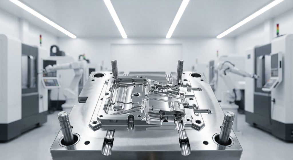
3. Review core, cavity and machining access together
The core and cavity form the part's internal and external geometry through their combined mold surfaces. Their arrangement also affects release, access for machining, fitting, cooling and service. A deep, narrow feature can require a different route from an accessible open surface.
CNC machining, EDM, replaceable inserts and changes to the parting strategy are options to evaluate, not automatic cost rankings. An insert might improve access and repairability while adding interfaces that need support and control. A geometry change might simplify cutting but affect part function or appearance.
| Design choice | Potential tooling consequence | Evidence needed before choosing |
|---|---|---|
| Change release direction | Different parting, shutoffs or actions | Part function, visible zones and release review |
| Open access to a deep feature | More practical cutting or finishing | Geometry, drawing requirements and machining concept |
| Use a replaceable insert | Additional interfaces but improved service access | Support, alignment, cooling and replacement plan |
| Simplify an internal detail | Fewer difficult surfaces or operations | Assembly, strength and acceptance review |
The comparison should explain a specific feature. It should not rely on an unsupported statement that one process is always faster or that a particular machine guarantees a finished-part tolerance.
4. Treat walls, ribs and cooling as a connected problem
Local mass, wall transitions, ribs and bosses affect filling, packing, cooling and release. Coring a thick region can change these conditions, but the revised structure still has to carry its load and support its assembly interface.
Do not thin a wall simply to reduce resin mass. The change may increase filling difficulty, alter stiffness or require different gating and process development. Conversely, unnecessary local thickness may create avoidable thermal and appearance risks.
Mold cooling and sink-mark troubleshooting explain related mechanisms. Material data and general design guidance are starting inputs; the released choice should be reviewed for the actual resin grade, geometry and acceptance plan.
5. Specify finish and inspection where they are needed
Mark the cosmetic surfaces and define the intended finish, texture, gate witness and viewing conditions. Texture can affect the release strategy and draft requirements. Polishing, texturing and any specified post-processing should be distinguished in the quotation.
Apply dimensional requirements to the function, datums and measurement method. An unnecessarily broad demand for tight tolerances can add tooling and inspection effort without improving the part's useful performance. Relaxing a critical interface without engineering approval creates the opposite risk.
The molding tolerance guide can help structure the acceptance discussion. A certificate, CMM machine or tool-steel specification does not establish a universal tolerance for every feature.

6. Compare cavity plans and assembly alternatives
More cavities can increase identical-part output per cycle, while also changing the mold, press and maintenance requirements. The right comparison includes the expected release pattern and usable production capacity. Family tooling adds part-mix and demand-balancing questions.
Similarly, combining components may remove an assembly operation but create more complicated geometry, tooling or inspection. An insert-molded design may replace a later assembly step while adding insert supply, loading, shutoff and retention checks. Compare the complete route rather than one removed operation.
| Alternative | Work that may change | Requirement to protect |
|---|---|---|
| More identical cavities | Tool investment, press fit, inspection and output | Cavity-specific conformity and realistic demand |
| Family mold | Part balancing and component availability | Assembly quantities and each component's acceptance |
| Molded-in assembly feature | Tooling, release and joining operations | Retention, serviceability and functional life |
| Insert molding | Insert supply, loading, shutoff and validation | Location, retention and interface requirements |
7. Approve changes against a controlled baseline
For each proposed change, record the old and new revision, the requirement being protected, the manufacturing rationale and the validation work. Ask for the revised quotation where the scope changes. Do not treat an attractive directional argument as a demonstrated saving.
Protolabs' design-to-cost guidance discusses geometry, actions, finishes and tooling choices. Its process-specific examples are useful context, not WOKE Molds pricing or a substitute for a project review.
WOKE Molds designs and builds molds in our own factory in Dongguan. Formal DFM normally follows project kickoff. Share the controlled part files and the alternatives you want reviewed so that function, tooling and acceptance can be considered together.
Frequently asked questions
Is eliminating an undercut always worth doing?
No. The feature may provide necessary retention, sealing or assembly behavior. Compare the functional consequence with the mechanism, handling and validation required to manufacture it.
Does a smoother surface always cost more?
There is no universal ranking. Accessibility, surface area, geometry, steel condition and the specified finish process affect the work. Define the actual visible zones and finish requirement rather than using a broad appearance label.
Can one part replace several assembled components?
Sometimes, but compare the revised mold and part complexity with the removed joining operations. Function, assembly access, repair, material compatibility and inspection can change the result.
Will a multi-cavity mold reduce the unit price?
It may improve output economics for a suitable program, but the investment, press, cycle, utilization and quality assumptions must support the choice. It is not an automatic saving for every part or release pattern.
What is the safest time to review design-to-cost changes?
Review alternatives before the tool design is released where practical. Changes later in the project are still possible, but their effect on steel, components, trials and approval must be evaluated against the current baseline.