
CMM Measurement: How to Get Accurate Results the Right Way
CMM measurement uses a coordinate measuring machine to record points on a part’s surface in three dimensions and compare them with the drawing or 3D model. A probe touches or scans the part, the machine records each point’s X, Y and Z position, and software calculates sizes, positions and geometric tolerances such as flatness, true position and profile.
For buyers, CMM measurement is the evidence behind a dimensional report. However, a CMM report is only as good as its setup, alignment and program. For example, a part measured on the wrong datum can pass every dimension in the report and still fail in assembly. In this guide, we explain how CMM measurement works, how accurate it is, and how it connects to gauge R&R, Cp and Cpk and tolerance stack-ups in quality control and inspection.
CMM measurement is a dimensional inspection method in which a coordinate measuring machine probes points on a part and software evaluates them against nominal geometry and GD&T callouts. It measures complex features, datums and geometric tolerances that hand gauges cannot, and its accuracy is specified under the ISO 10360 series. CMM results support first article inspection, PPAP dimensional results, capability studies and troubleshooting of molded and machined parts.
In short: CMM measurement turns a drawing’s datums and tolerances into numbers you can trust, if the setup is right.
Key points:
- What it measures: sizes, positions and GD&T such as flatness, profile and true position.
- Accuracy: depends on the machine, probe, temperature and part setup.
- Use: FAI, PPAP, capability studies and root-cause analysis.
What Is CMM Measurement?
CMM measurement is the process of measuring a part’s geometry by collecting coordinate points with a probe and comparing them with nominal values. The CMM, or coordinate measuring machine, moves the probe along three axes and records the position of every touch.
Software then fits geometric elements to the points: planes, circles, cylinders, cones and free-form surfaces. From those elements, it reports results such as:
- Diameters, lengths and angles
- Position of holes relative to datums
- Flatness, parallelism and perpendicularity
- Profile of a surface against the CAD model
Therefore, CMM measurement is the standard method for parts with GD&T callouts, complex shapes or many related features.
Key Takeaway: Think of CMM measurement as measuring geometry, not just dimensions. Its real value is checking how features relate to datums.
How Does a CMM Measuring Machine Work?
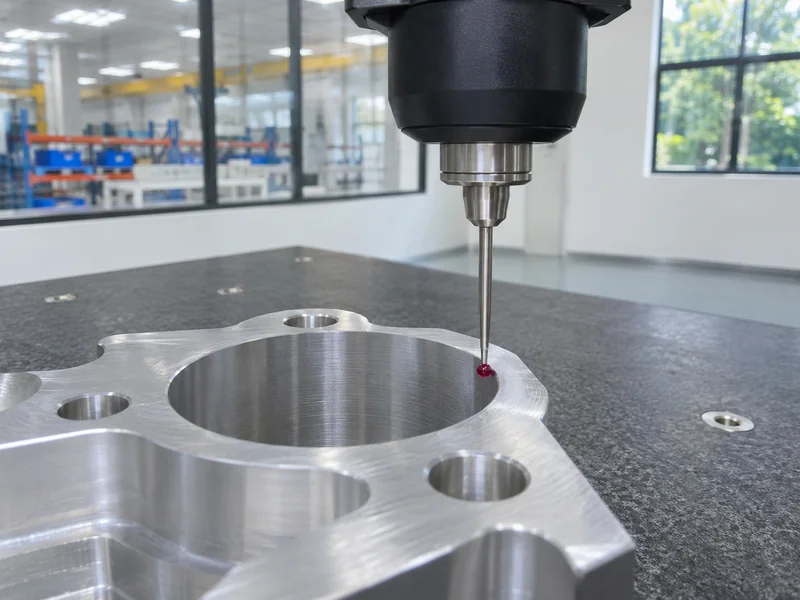
A CMM measuring machine works by moving a probe precisely in X, Y and Z over a stable reference surface, usually a granite table, and recording each contact point.
Main components
- Structure: bridge, gantry, cantilever or horizontal arm
- Probe system: touch-trigger probes, scanning probes or optical sensors
- Stylus: often a ruby ball on a stem, chosen to reach the features
- Software: builds alignments, measures features and creates reports
Typical measurement steps
- Clean and stabilize the part at the room temperature.
- Fix the part without distorting it.
- Measure datum features and build the part alignment.
- Run the measurement program for each characteristic.
- Evaluate results and create the report.
Our core facility uses a Leader CMM with a 1,200 × 1,000 × 800 mm measuring range, which covers most mold plates, inserts and machined parts we inspect.
Key Takeaway: The alignment step decides the result. Always check that the CMM alignment uses the drawing’s datums in the right order.
What Can CMM Measurement Check on Molded and Machined Parts?
CMM measurement can check almost every dimensional and geometric requirement on molded and machined parts, as long as the probe can reach the feature.
| Feature | CMM suitability | Notes |
|---|---|---|
| Hole position and diameter | Excellent | Core use of CMM |
| Flatness and parallelism | Excellent | Fixturing must not bend the part |
| Surface profile vs CAD | Very good | Scanning gives better coverage |
| Small internal features | Good | Needs suitable stylus length and size |
| Thread pitch diameter | Limited | Thread gauges are usually better |
| Very soft or flexible parts | Limited | Contact force can deflect the part |
| Cosmetic defects | Not suitable | Use visual inspection |
For molded parts, warpage and shrinkage often show up as flatness, profile and position errors. As a result, CMM measurement is a key tool in mold trials and corrections.
Key Takeaway: Use CMM measurement for geometry and datums, and simpler gauges for threads, go/no-go fits and cosmetics.
How Accurate Is CMM Measurement?
CMM measurement accuracy depends on the machine’s specification, the probe, the environment and the part setup. Machine accuracy is specified as a maximum permissible error under the ISO 10360 series of standards.
In practice, the total measurement uncertainty is larger than the machine’s specification, because of:
- Temperature: parts and machines expand with heat, so measuring a warm part adds error.
- Fixturing: clamping can bend thin or flexible parts.
- Probe and stylus: long, thin styli bend; ball size affects small features.
- Alignment and program: wrong datums or too few points change the result.
A common rule is that the measurement uncertainty should be small compared with the tolerance, often one-tenth or less. For example, a ±0.02 mm tolerance needs a much more capable setup than a ±0.2 mm tolerance.
Key Takeaway: Ask how the measurement was set up, not just which machine was used. Temperature, fixturing and alignment matter as much as the CMM itself.
When Is CMM Measurement Worth the Cost?
CMM measurement is worth the cost when the part has GD&T, complex geometry, many related features or when a dimensional report is contractually required. It costs more time than hand gauging, so it should be used where it adds value.
Use CMM measurement for:
- First article inspection and PPAP dimensional results
- Mold trial corrections and steel-safe adjustments
- Capability studies on key characteristics
- Root-cause analysis of assembly problems
Use simpler gauges for:
- High-frequency production checks of a few key dimensions
- Go/no-go checks of holes and threads
- Visual and cosmetic inspection
Key Takeaway: Use the CMM to qualify the process and simpler gauges to monitor it. That balance controls inspection cost.
How Does Gauge R&R Apply to CMM Measurement?
Gauge R&R applies to CMM measurement by showing how much of the observed variation comes from the measurement system rather than the parts. It is a core part of measurement system analysis.
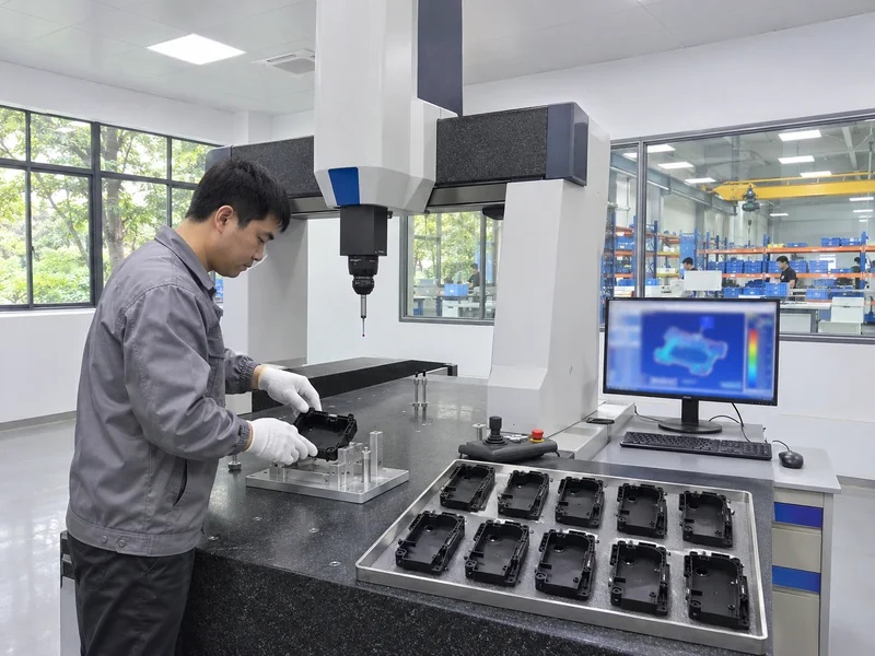
A typical study:
- Select about 10 parts that represent the process range.
- Measure each part several times, often by more than one operator or setup.
- Calculate repeatability (equipment variation) and reproducibility (operator or setup variation).
Common acceptance guidance:
- Below 10% of tolerance or process variation: acceptable
- 10–30%: may be acceptable depending on the application and cost
- Above 30%: not acceptable; improve the measurement system
For CMM measurement, reproducibility often comes from fixturing and alignment rather than operators. Therefore, a fixed program and a dedicated fixture improve gauge R&R results.
Key Takeaway: Run gauge R&R before capability studies. A noisy measurement system can make a capable process look poor.
How Do Cp and Cpk Use CMM Measurement Data?
Cp and Cpk use CMM measurement data to show whether a process can produce parts within tolerance consistently. Cp compares the tolerance width with process spread; Cpk also considers how centered the process is.
- Cp = tolerance width ÷ (6 × standard deviation)
- Cpk = the smaller of (upper limit − mean) and (mean − lower limit), divided by (3 × standard deviation)
Common targets are Cpk ≥ 1.33 for ongoing production and higher, often 1.67, for initial studies in automotive programs. For molded parts, each cavity is a separate process stream, so capability should be checked per cavity. Our article on PPAP level 3 requirements explains how capability studies fit a submission.
Key Takeaway: Calculate capability per cavity and only after the gauge study passes. Pooled data can hide a bad cavity.
How Do Tolerance Stack-Ups Affect Gasket Compression?
Tolerance stack-ups affect gasket compression because every dimension between the sealing faces adds variation to the gap the gasket must fill. If the stack-up is too wide, some assemblies under-compress and leak, while others over-compress and damage the gasket.
A simple approach:
- List every dimension in the chain between the two sealing faces.
- Calculate the worst-case gap by adding all tolerances.
- Calculate a statistical (RSS) gap by combining tolerances as the square root of the sum of squares.
- Compare both with the gasket’s allowed compression range.
For example, a molded cover, a machined housing and a gasket groove might each add ±0.1 mm. Worst case, the gap varies by ±0.3 mm; statistically, closer to ±0.17 mm. CMM measurement data from real parts then shows where the actual parts fall.
Key Takeaway: Check gasket compression with real CMM data, not only drawing tolerances. Real parts often sit off-center in their tolerance band.
What Should a CMM Measurement Report Include?
A CMM measurement report should include enough information to repeat the measurement and trust the result.
- Part number, revision and cavity or serial number
- Ballooned drawing reference for each characteristic
- Nominal, tolerance, measured value and deviation
- Pass or fail for each characteristic
- Datum alignment used and the measurement program reference
- Temperature and date of measurement
- Name or ID of the inspector
At WOKE Molds, full dimensional or CMM reports, FAI and inspection reports are supplied when the project requires them. For broader inspection practice, see our mold inspection standards guide.
Key Takeaway: Ask for the alignment and conditions, not only the numbers. They make a CMM report repeatable.
FAQ
- Q: What does CMM stand for?
- CMM stands for coordinate measuring machine, a device that measures part geometry by recording 3D points with a probe.
- Q: How accurate is CMM measurement?
- Machine accuracy is specified under ISO 10360, but real uncertainty also depends on temperature, fixturing, probe choice and alignment.
- Q: What can a CMM measure?
- Sizes, hole positions, flatness, profile and other GD&T requirements on molded, machined and cast parts.
- Q: Is CMM measurement needed for every part?
- No. It is best for first articles, complex geometry and GD&T. Simple gauges are faster for routine production checks.
- Q: What is gauge R&R for a CMM?
- It is a study that shows how much measurement variation comes from the CMM setup and repeat measurements, compared with the tolerance.
Conclusion
CMM measurement gives reliable geometry data when the alignment, fixturing and conditions are right. Use it to qualify parts and processes, and support it with gauge R&R and capability studies. To plan inspection for your part, send your 3D model and 2D drawing to our quality team.