
GD&T Position Tolerance: Datums, MMC and Calculation
GD&T position tolerance controls where a feature, usually a hole or pin, may sit relative to datums. Instead of plus/minus coordinates, it defines a tolerance zone, often a cylinder, around the true position. For machined hole patterns that must match a mating part, position tolerance is the clearest way to state what really matters: that bolts or pins will assemble.
Used well, it can even make parts cheaper. For example, a coordinate tolerance of ±0.1 mm in X and Y creates a square zone, while a 0.28 mm diameter position zone covers the same corners and gives 57% more usable area. Used badly, however, it adds inspection cost without adding function. In this guide, we explain GD&T position tolerance for machined hole patterns: datums, tolerance zones, MMC bonus tolerance, calculating values from fasteners, machining strategy and inspection. Symbols and rules follow ISO 1101 and ASME Y14.5.
GD&T position tolerance defines a zone, usually cylindrical, centered on the feature’s theoretically exact (basic) location relative to datums A, B and C. The feature’s axis must lie inside the zone. A diameter zone gives about 57% more area than the equivalent square ± coordinate zone. With the maximum material condition (MMC) modifier, the tolerance grows as the hole departs from its smallest size (bonus tolerance). For a floating fastener, position tolerance ≈ hole MMC size − fastener MMC size; for a fixed fastener, the available difference is split between the two parts.
In short: position tolerance states assembly function directly, gives more usable tolerance than ± coordinates and can be calculated from the fastener fit.
Key points:
- Zone: a cylinder around the true position.
- Datums: define how the part is located for measurement.
- MMC: adds bonus tolerance as holes get larger.
What Is GD&T Position Tolerance?
GD&T position tolerance is a geometric tolerance that limits how far a feature’s center or axis may deviate from its true position. The true position is defined by basic dimensions (shown in boxes) measured from datums.
A position callout includes:
- Position symbol (a circle with crosshairs)
- Diameter symbol for a cylindrical zone
- Tolerance value, such as 0.2
- Modifier, such as MMC (Ⓜ), if used
- Datum references, such as A, B, C
For example, “⌖ Ø0.2 Ⓜ A B C” on a 4-hole pattern means each hole axis must lie within a 0.2 mm diameter zone at MMC, located from datums A, B and C. The rules are defined in standards from ISO, mainly ISO 1101 and ISO 5458.
Key Takeaway: Position tolerance only makes sense with clear datums. Define them first.
Why Is GD&T Position Tolerance Better Than ± Coordinates?
GD&T position tolerance is better than ± coordinates because it matches how holes actually assemble and gives more usable tolerance.
Advantages:
- Round zone: a hole can move equally in any direction, as a fastener allows.
- More area: a Ø0.28 zone contains the full ±0.1 square plus extra area.
- Datum clarity: measurement setup is defined, so suppliers and inspectors agree.
- Bonus tolerance: with MMC, larger holes get more position tolerance.
For example, a hole at +0.1/+0.1 from nominal is 0.141 mm off true position. In a ±0.1 square it passes, but at +0.12/0 it fails, even though it is closer. A Ø0.28 position zone accepts both. Our CNC machining services machine to GD&T drawings, with tolerances controlled per drawing.
Key Takeaway: Convert critical hole patterns from ± coordinates to position tolerance. It is more functional and often cheaper.
How Do Datums Work With GD&T Position Tolerance?
Datums work with position tolerance by fixing the part in a defined way before measuring hole locations.
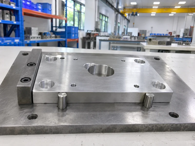
The common 3-2-1 scheme:
- Datum A (primary): a face that the part sits on; 3 points of contact.
- Datum B (secondary): an edge or hole; 2 points of contact.
- Datum C (tertiary): another edge or hole; 1 point of contact.
Choose datums that match how the part mounts in the assembly. For example, if a cover mounts on its back face and locates on two dowel holes, those should be the datums, not the outer edges. Our guide to CMM measurement explains how datums are set up on a CMM.
Key Takeaway: Pick datums from the assembly, not from the drawing border.
How Does MMC Bonus Tolerance Work?
MMC bonus tolerance works by allowing more position tolerance when a hole is made larger than its smallest allowed size.
How it works:
- At MMC (smallest hole), only the stated position tolerance applies.
- As the hole grows, the extra size is added to the position tolerance.
- At LMC (largest hole), the bonus is maximum.
Example:
- Hole size: Ø6.6 +0.2/0 (MMC Ø6.6, LMC Ø6.8)
- Position: Ø0.2 at MMC
- If the hole measures Ø6.7, position tolerance = 0.2 + 0.1 = Ø0.3
Bonus tolerance lets the machinist use the whole size tolerance productively. However, MMC should only be used where the fit is clearance-based, not for press fits or precision locations.
Key Takeaway: Use MMC on clearance holes for fasteners. Avoid it on dowel and bearing holes.
How Do You Calculate Position Tolerance for a Hole Pattern?
You calculate position tolerance for a hole pattern from the fastener size and the hole size, using the floating or fixed fastener formula.
Floating fastener (bolt passes through clearance holes in both parts, nut on the end):
- T = H − F
- H = hole MMC diameter, F = fastener MMC diameter
Fixed fastener (screw threads into one part):
- T1 + T2 = H − F
- Split the total between the two parts
Worked example (floating, M6 bolts):
- Fastener MMC: Ø6.0
- Clearance hole MMC: Ø6.6
- Position tolerance: Ø0.6 for each part
For example, if one part is threaded (fixed fastener), the same 0.6 is shared, such as Ø0.3 for each part. In addition, projected tolerance zones are used for threaded holes where perpendicularity affects assembly.
Key Takeaway: Calculate position tolerance from the fastener. Do not copy a default value.
How Do You Machine Hole Patterns to True Position?
You machine hole patterns to true position by holding the part on its datums, machining related holes in one setup and checking the machine’s accuracy.
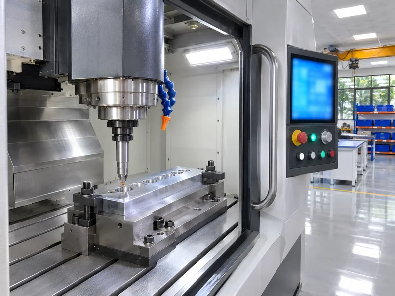
Machining practice:
- Locate on datums: fixture the part the way the drawing defines.
- One setup: drill or bore all related holes without re-clamping.
- Spot drill first for accurate starts.
- Bore or ream precision holes rather than only drilling.
- Temperature control: long parts expand with heat.
For example, a pattern of four bearing holes machined in one setup on a CNC milling center holds position far better than holes drilled in two setups. Machine capability is not the same as finished-part tolerance, which is verified per drawing.
Key Takeaway: Put related holes in one setup. Re-clamping adds position error.
How Is Position Tolerance Inspected?
Position tolerance is inspected by measuring hole centers relative to the datum reference frame, usually on a CMM, or with functional gauges for MMC callouts.
Inspection methods:
- CMM: measures each hole, calculates position from datums, applies bonus.
- Functional gauge: pins at virtual size check MMC patterns quickly.
- Optical or vision systems: for small or thin parts.
- Reports: list actual position, size and bonus for each hole.
For example, a functional gauge for a 4-hole MMC pattern lets a production operator check every part in seconds. Our quality control and inspection process uses a CMM with a 1,200 × 1,000 × 800 mm measuring range, and reports are supplied on request.
Key Takeaway: Agree the inspection method when you agree the tolerance. MMC callouts suit functional gauges.
FAQ
- Q: What is GD&T position tolerance?
- A tolerance zone, usually cylindrical, around the true position of a feature, located from datums.
- Q: Why use position tolerance instead of ± tolerances?
- It matches assembly function and gives about 57% more usable area than a square ± zone.
- Q: What is bonus tolerance?
- Extra position tolerance allowed when a feature with an MMC modifier departs from its MMC size.
- Q: How do you calculate position tolerance for bolts?
- For floating fasteners, T = hole MMC − fastener MMC; for fixed fasteners, split that value between parts.
- Q: How is position tolerance measured?
- Usually on a CMM relative to the datums, or with a functional gauge for MMC callouts.
Conclusion
GD&T position tolerance states hole pattern requirements in the way parts actually assemble. Choose datums from the assembly, calculate tolerance from the fasteners, use MMC on clearance holes and machine related holes in one setup. To review a GD&T drawing, send your 3D model and 2D drawing to our engineers.