
Hot Runner Manifold: Balancing, Heaters and Expansion
A hot runner manifold is the heated block that distributes molten plastic from the machine nozzle to each hot runner nozzle in the mold. Its layout decides whether every gate receives melt at the same pressure, temperature and time. It also decides how easy the system is to heat, monitor and repair over the mold’s life.
A poor layout causes problems that process settings cannot fix. For example, a manifold with unequal flow lengths can fill one cavity before another, so part weights differ in every shot. Likewise, a manifold with heaters that cannot be reached without removing the whole mold turns a 30-minute repair into a day of downtime. In this guide, we explain how to lay out a hot runner manifold for balance and service, including flow balance, heater and thermocouple zone maps, thermal expansion and repair access. For the wider choice, see our guide to hot runner vs cold runner molds.
A hot runner manifold should be laid out with naturally balanced flow paths (equal length and diameter to each nozzle), heaters placed to give uniform temperature along every channel, a clear zone map that links each heater and thermocouple to a controller zone, allowance for thermal expansion so nozzles align at operating temperature, and access to heaters, thermocouples and wiring without full mold disassembly. Channel sizes are matched to the resin and shot size, and dead spots are avoided to prevent degradation and color-change problems.
In short: balance the flow, map every heating zone, design for expansion and plan repair access from the start.
Key points:
- Balance: equal flow length and diameter to each nozzle.
- Zone map: every heater and thermocouple documented.
- Service: heaters and wiring reachable without full teardown.
What Is a Hot Runner Manifold?
A hot runner manifold is a heated steel block with internal channels that carry molten plastic from a central inlet to several nozzles. It sits inside the mold, insulated from the cooled mold plates.
Main parts of a hot runner system:
- Sprue bushing or inlet nozzle, connected to the machine nozzle
- Manifold, with flow channels and heaters
- Drops or nozzles, which deliver melt to each gate
- Heaters and thermocouples, for each temperature zone
- Controller, which regulates each zone
- Valve actuators, if valve gates are used
Hot runner systems from suppliers such as YUDO, Mold-Masters, HASCO or Synventive are used per customer requirement in our injection mold manufacturing projects.
Key Takeaway: The manifold is the heart of the hot runner. Its layout matters as much as the nozzle choice.
How Do You Balance a Hot Runner Manifold?
You balance a hot runner manifold by giving every nozzle the same flow length, channel diameter and number of turns from the inlet.
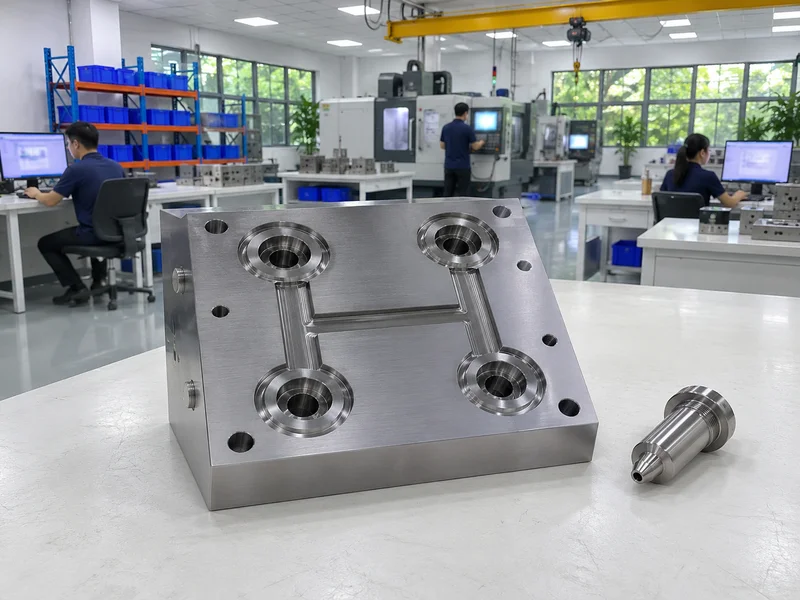
Balancing methods:
- Natural balance: symmetrical H-pattern or X-pattern layouts
- Equal turns: the same number of corners to each nozzle
- Channel sizing: matched to flow rate and pressure drop
- Rheological balance: avoiding shear imbalance at channel splits
- Simulation: flow analysis to check balance before machining
For example, an 8-drop manifold in an H-pattern gives equal paths to all nozzles. A “fishbone” layout with nozzles along one line, in contrast, gives shorter paths to the nearest nozzles, so they fill first. Our guide to mold flow analysis explains how balance is simulated.
Key Takeaway: Ask for the manifold layout drawing with flow lengths. Unequal paths show up in part weights.
How Should Heaters Be Laid Out on a Hot Runner Manifold?
Heaters should be laid out on a hot runner manifold so every channel stays at the same temperature, including ends and corners that lose more heat.
Heater layout points:
- Tubular or cartridge heaters along the channels
- Extra heat near ends and supports, where heat is lost to the mold
- Separate zones for the manifold and each nozzle
- Thermocouples placed to read the channel temperature, not the heater surface
- Insulation through air gaps and minimal contact points
For example, the end of a long manifold may run 10–15 °C cooler than its center if heaters are evenly spaced. As a result, the end nozzles may fill slowly. Adding heater density near the ends solves it.
Key Takeaway: Ask for a thermal check, such as a temperature map at heat-up, during the mold trial.
What Should a Heater and Thermocouple Zone Map Include?
A heater and thermocouple zone map should show every heating zone, its heater, its thermocouple, its controller channel and its connector pin.
A complete zone map includes:
- Zone number for each manifold and nozzle zone
- Heater type, power and voltage
- Thermocouple type and position
- Connector and pin assignment
- Wiring route inside the mold
- Set temperature range from the trial
For example, if zone 5 overheats, a clear map shows whether it is a heater, thermocouple or wiring issue, and which connector pin to test. Without it, troubleshooting means opening the mold. Electrical safety for heater wiring follows standards such as those from the IEC.
Key Takeaway: Keep the zone map with the mold and the controller. It is essential for every repair.
How Does Thermal Expansion Affect Manifold Layout?
Thermal expansion affects manifold layout because the manifold heats to melt temperature while the mold plates stay cooler. Therefore, the manifold grows relative to the plates.
Design points:
- Calculate expansion from the center to each nozzle at operating temperature
- Offset nozzle positions when cold, so they align when hot
- Allow sliding at nozzle contact faces, or use fixed nozzles with floating manifolds
- Control preload at support pads, so seals work when hot
- Heat-up sequence: follow the supplier’s procedure to avoid leaks
For example, a steel manifold 400 mm long, heated about 200 °C above the mold plates, can grow by roughly 1 mm overall. Without that allowance, nozzles misalign and leak. Our guide to valve gate injection molding explains why alignment is especially important for valve pins.
Key Takeaway: Leaks at the nozzle seat usually come from wrong expansion allowance or heating sequence.
How Do You Plan Hot Runner Manifold Repair Access?
You plan hot runner manifold repair access by arranging plates, wiring and components so the most common repairs can be done without removing the mold or the whole hot half.
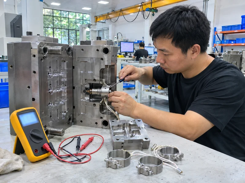
Repair access requirements:
- Nozzle heaters and thermocouples reachable from the parting line where possible
- Wiring channels with covers, not buried under plates
- Connectors on the outside of the mold, labeled and documented
- Lifting points for the hot half and manifold
- Spare heaters and thermocouples available for critical molds
For example, a nozzle tip heater that can be changed from the parting line takes minutes. In contrast, one that requires removing the clamp plate takes hours. Our guide to mold maintenance explains planned service, and paid spare parts such as heaters are available on request.
Key Takeaway: Ask which repairs can be done in the press. That list shows how much downtime to expect.
How Should a Hot Runner Manifold Be Validated at Trial?
A hot runner manifold should be validated at trial by checking temperature, balance, leaks and color change.
Validation checks:
- All zones reach set temperature and hold steady
- Short-shot study to check fill balance between nozzles
- Part weight per cavity within the agreed range
- No leaks at nozzle seats after heat-up and running
- Color or material change completed within an agreed number of shots
For example, if one cavity is consistently lighter, adjusting its nozzle temperature by a few degrees may balance it. A large adjustment, however, points to a layout problem. Our guide to multi-cavity injection molding explains cavity balance checks.
Key Takeaway: Record zone temperatures and part weights per cavity in the trial report. They are the baseline for future problems.
FAQ
- Q: What is a hot runner manifold?
- A heated block that carries molten plastic from the machine nozzle to each hot runner nozzle in the mold.
- Q: How do you balance a hot runner manifold?
- By giving every nozzle equal flow length, channel diameter and number of turns, and checking with simulation and trials.
- Q: What is a hot runner zone map?
- A document linking each heater and thermocouple to its controller zone, connector pin and wiring route.
- Q: Why do hot runner nozzles leak?
- Usually because of wrong thermal expansion allowance, low preload or an incorrect heat-up sequence.
- Q: How can hot runner repairs be made faster?
- By designing access to heaters, thermocouples and wiring from the parting line and keeping spare parts.
Conclusion
A hot runner manifold works well when its flow is balanced, its heating is mapped and its components can be serviced without long downtime. Plan the layout, zone map, expansion and access together, and validate them at the trial. To review a hot runner mold, send your 3D model and 2D drawing to our engineers.