
Tolerance for Slip Fit: Sizing Shafts and Bushings
A tolerance for slip fit defines how much clearance a shaft and hole must have so the parts slide together by hand but still locate accurately. Common slip fits in the ISO system include H7/g6 and H7/h6. Getting the tolerance for slip fit right depends not only on the numbers, but also on how the turned and bored features are made: long shafts deflect, thin bushings distort, and burrs or grooves can block assembly.
Many slip fit problems come from details around the fit. For example, a shaft within tolerance may still not slide into its bore because a parting-off burr or a missing relief groove catches the edge. Likewise, a long, thin shaft may be in tolerance at the ends but oversize in the middle due to deflection. In this guide, we explain how to size a tolerance for slip fit and how turning details, including knurling, internal grooves, long shafts, thin-wall bushings, parting-off burrs and shoulder reliefs, affect it. For turning services, see our CNC turning page.
A tolerance for slip fit uses a hole-basis fit such as H7/g6 (small guaranteed clearance, easy sliding) or H7/h6 (zero to small clearance, precise location). For a 20 mm nominal size, H7/g6 gives roughly 0.007–0.041 mm clearance and H7/h6 about 0–0.034 mm. The fit is only achieved in assembly if the turned features are straight, round and free of burrs, with chamfers or lead-ins, shoulder relief grooves and controlled deflection on long shafts. Thin-wall bushings need special workholding to keep bores round.
In short: choose H7/g6 or H7/h6 for slip fits, then control straightness, roundness, burrs and reliefs so the fit works in assembly.
Key points:
- Fits: H7/g6 for easy sliding; H7/h6 for precise location.
- Geometry: straightness and roundness matter as much as size.
- Details: chamfers, relief grooves and burr control.
What Is a Tolerance for Slip Fit?
A tolerance for slip fit is the combination of hole and shaft tolerances that guarantees a small clearance, so parts can be assembled and moved by hand without play that affects function.
| Fit (ISO 286) | Type | Typical clearance at Ø20 mm | Use |
|---|---|---|---|
| H7/g6 | Sliding fit | about 0.007–0.041 mm | Sliding parts, pins, guides |
| H7/h6 | Locational clearance | about 0–0.034 mm | Precise location, spigots |
| H8/f7 | Running fit | about 0.020–0.074 mm | Rotating shafts with lubrication |
Fit tables come from ISO 286 published by ISO. For example, a locating spigot that must center a flange typically uses H7/h6, while a guide pin that slides often uses H7/g6.
Key Takeaway: Pick the fit by function: sliding, locating or running.
How Do You Size a Tolerance for Slip Fit?
You size a tolerance for slip fit by choosing the fit class, then checking it against temperature, materials and the manufacturing method.
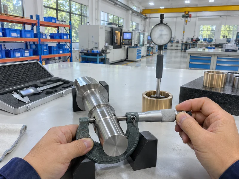
Steps:
- Define function: slide, locate or rotate.
- Choose a fit class from ISO 286, such as H7/g6.
- Check materials: different thermal expansion changes clearance.
- Check operating temperature: clearance at service temperature, not only at 20 °C.
- Check lubrication and contamination needs.
- Confirm manufacturability of the tolerance grades.
For example, an aluminum housing with a steel shaft gains clearance as it warms, because aluminum expands more. A fit that is snug at room temperature may become loose at 80 °C. Our guide to GD&T position tolerance explains how hole patterns relate to fits.
Key Takeaway: Check the fit at operating temperature when the materials differ.
How Does Long Shaft Turning Deflection Affect Slip Fits?
Long shaft turning deflection affects slip fits because the cutting force bends a slender shaft, so the middle is cut larger than the ends.
Signs and causes:
- Barrel shape: larger diameter in the middle
- High length-to-diameter ratio, often above about 10:1
- Insufficient support at the free end
Control methods:
- Tailstock support for longer shafts
- Steady rest or follow rest for very slender shafts
- Light finishing passes with sharp tools
- Grinding for precision shafts after turning
For example, a 300 mm long, 12 mm diameter shaft turned without support can be several hundredths oversize in the middle. A tailstock and light finish pass keep it within an h6 tolerance. Our guide to CNC lathe vs CNC mill explains turning setups.
Key Takeaway: For slender shafts, specify straightness or cylindricity, not only diameter.
How Do You Keep Thin-Wall Bushings Round?
You keep thin-wall bushings round by avoiding clamping distortion and heat during machining.
Methods:
- Soft jaws bored to the part diameter
- Collets or expanding mandrels for even pressure
- Six-jaw chucks instead of three-jaw
- Light finishing cuts after roughing
- Finishing the bore and OD in one setup where possible
For example, a bronze bushing with 1 mm walls clamped in a three-jaw chuck may be round while clamped, but becomes three-lobed after release. A collet or soft jaws prevent this. Roundness should be specified when the bushing must slip over a shaft precisely.
Key Takeaway: Add a roundness tolerance on thin-wall bushings. Size alone can pass a lobed part.
How Do Burrs, Chamfers and Relief Grooves Affect Assembly?
Burrs, chamfers and relief grooves affect assembly because they decide whether parts can actually slide together at the fit’s tight clearance.
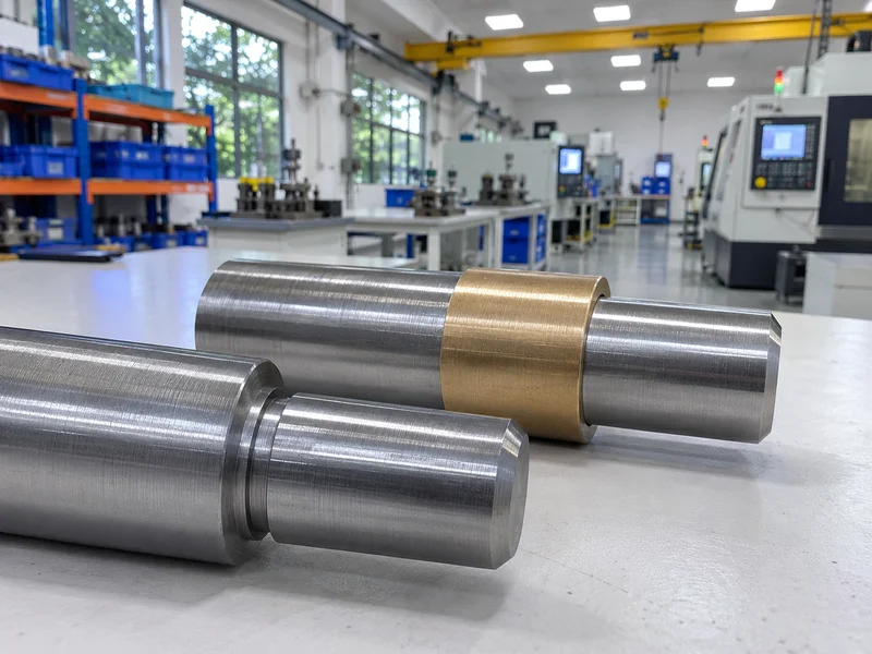
Turning details:
- Parting-off burr: a small pip or ring left when the part is cut off; must be removed.
- Chamfers or lead-ins: guide the shaft into the bore.
- Shoulder relief groove: an undercut at a shoulder, so the mating part seats fully against the face.
- Internal grooving: relief or retaining ring grooves inside bores; check burrs at groove edges.
- Knurling: raises material; never on a slip-fit diameter unless intended.
For example, a shaft with a sharp corner at the shoulder cannot seat a bushing with a square edge, so the bushing stops short. A relief groove solves it. Our CNC machining services include deburring and edge-break requirements per drawing.
Key Takeaway: Draw chamfers, relief grooves and edge-break notes. They make the fit assemble.
How Should Slip Fit Features Be Inspected?
Slip fit features should be inspected for size, form and condition, using methods suited to the tolerance.
Inspection methods:
- Micrometers for shaft diameters
- Bore gauges or plug gauges for holes
- Go/no-go gauges for production checks
- Roundness and cylindricity on a form tester or CMM where specified
- Visual check for burrs and damaged edges
- Trial assembly for critical pairs
For example, a go/no-go plug gauge for an H7 bore lets an operator check every part quickly. Our quality control and inspection process uses gauges and CMM measurement as required.
Key Takeaway: Use go/no-go gauges for slip fits in production. They are fast and match function.
FAQ
- Q: What is a slip fit tolerance?
- A shaft and hole tolerance combination that guarantees a small clearance so parts slide together by hand.
- Q: What is a typical slip fit?
- H7/g6 for sliding parts and H7/h6 for precise location.
- Q: How much clearance does H7/g6 give at 20 mm?
- Roughly 0.007–0.041 mm.
- Q: Why does a shaft within tolerance not fit?
- Often because of burrs, no chamfer, a sharp shoulder corner, or form errors like taper or out-of-roundness.
- Q: How do you stop long shafts deflecting during turning?
- Use tailstock or steady rest support, light finishing passes and sharp tools.
Conclusion
A tolerance for slip fit starts with the right ISO fit, but it only works when the turned features are straight, round, deburred and relieved. Specify form tolerances, chamfers and relief grooves, and inspect with gauges. To review a turned assembly, send your 3D model and 2D drawing to our engineers.