
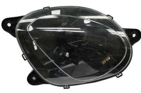
Covers, shells and enclosures
Integrate clips, bosses, ribs, sealing rims and cosmetic faces into a repeatable molded component.
Focus: Flatness, assembly datums, wall transitions, gate location, visible weld lines, texture and ejection marks.
Plastic injection molding manufacturer · Shenzhen, China
Move from drawing and resin requirements to approved samples and repeat production of injection molded parts. WOKE Molds builds the molds in our Dongguan factory and molds the parts on 41 presses from 30 to 380 tons in our Shenzhen plant, certified to IATF 16949 and ISO 9001.
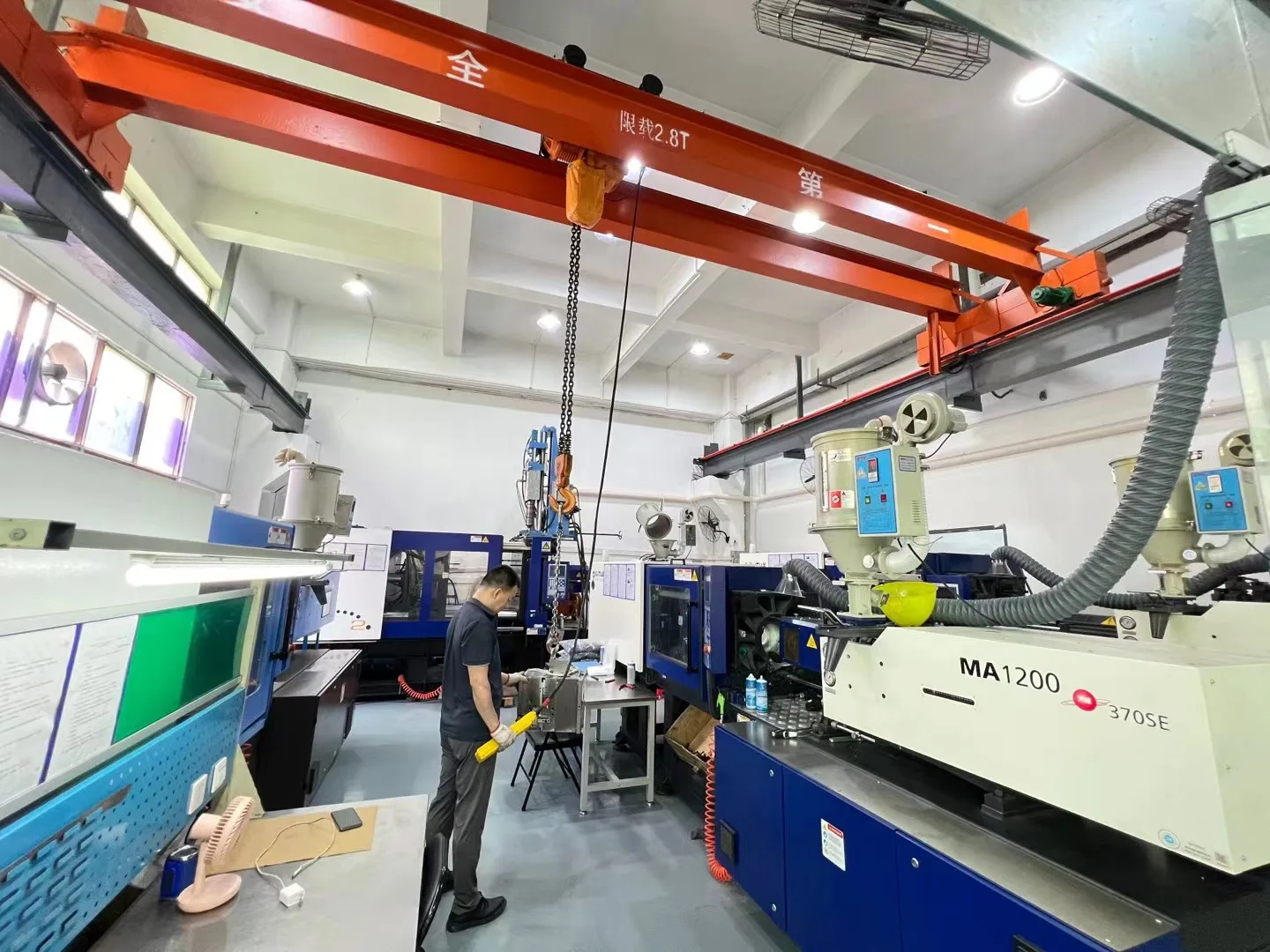
Parts production
Injection molding is valuable when geometry, material and forecast justify a dedicated tool and a controlled production route. The right starting point for custom plastic parts is not a machine list; it is the function, interfaces and acceptance risks of your part, from pilot lots to high volume injection molding.
Integrate clips, bosses, ribs, sealing rims and cosmetic faces into a repeatable molded component.
Focus: Flatness, assembly datums, wall transitions, gate location, visible weld lines, texture and ejection marks.
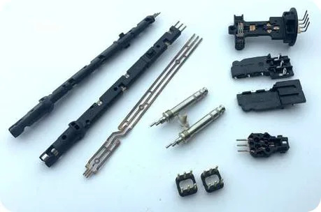
Hold molded geometry around contact positions and assembly interfaces in one repeatable component.
Focus: Contact location, shutoff and flash limits, venting, cavity consistency, handling and a workable datum/measurement method.
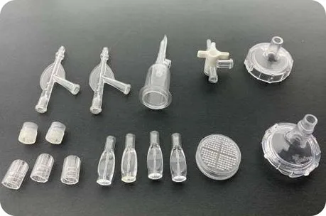
Combine molded geometry with a defined transparent appearance and assembly fit.
Focus: Resin and drying, surface protection, flow and gate marks, stress, scratch expectations, optical zones and packaging protection.
Metal-contact parts shown here point to a specialized insert-molding route; construction and acceptance requirements are reviewed separately.
Material direction
Candidate families include PP, ABS, PC, PA, POM, PBT, TPE, PC/ABS, PMMA, TPU, PPS, PEEK, LCP and PPA, including glass-filled, carbon-filled and flame-retardant grades. The working choice is narrowed to an exact grade around the part geometry, performance requirements, tool and press conditions.
For background before selecting a grade, compare common injection molding materials and engineering plastics and their properties, then confirm the application requirements against the selected supplier data.
Possible starting families PP, ABS or PC/ABS
PP often points toward chemical resistance, low density and living-hinge flexibility, but stiffness, heat resistance and creep must be checked by grade and geometry. ABS can favor stiffness and finish; PC/ABS can add impact and heat performance, with cost, stress and regulatory requirements still to resolve.
Possible starting families PC or PMMA
PC is often selected where impact resistance matters; PMMA can offer strong clarity and surface appearance. Scratch response, chemical/stress sensitivity, required optical quality, drying, gate/flow marks and handling determine the practical choice.
Possible starting families POM, PA or PBT
POM is a common direction for low friction and dimensional consistency; PA can bring toughness and wear performance but its moisture state can change dimensions and properties; PBT can support electrical and dimensional applications. Exact reinforcement, creep, shrinkage and measurement condition remain decisive.
Possible starting families TPE or TPU
TPE can suit soft-touch and flexible interfaces across a broad hardness range, while TPU can point toward abrasion resistance and toughness. Compression set, chemicals, temperature, adhesion or mechanical lock, color and surface feel must match the application.
Possible starting families PPS, PEEK, LCP or PPA
These families become relevant when sustained heat, strength, electrical behavior, chemical resistance or thin-flow requirements exceed commodity options. The actual load/temperature profile, reinforcement, moisture, flow, tool/process temperature, evidence, supply and total cost narrow the grade.
For moisture-sensitive resins, drying before molding and any finished-part conditioning or measurement state are separate controls. Agree the applicable grade guidance and acceptance condition instead of relying on one generic shop rule.
Engineering before tooling
An initial scope review checks whether the available files are sufficient for feasibility and quotation. After project kickoff, formal DFM converts the released part requirements into tooling and process decisions. Moldflow can support projects where flow, packing, cooling or warpage risk calls for deeper analysis.
Related engineering guides explain sink-mark troubleshooting and plastic shrinkage to support the part and process review.
QuestionCan the structure fill, cool and eject without avoidable sink, distortion or stress concentration?
Engineering actionReview transitions, rib/boss proportions, coring, local mass and how the feature carries load or accepts a fastener.
ValidationInspect appearance and key dimensions on trial parts; confirm fastening or assembly behavior where it is an acceptance requirement.
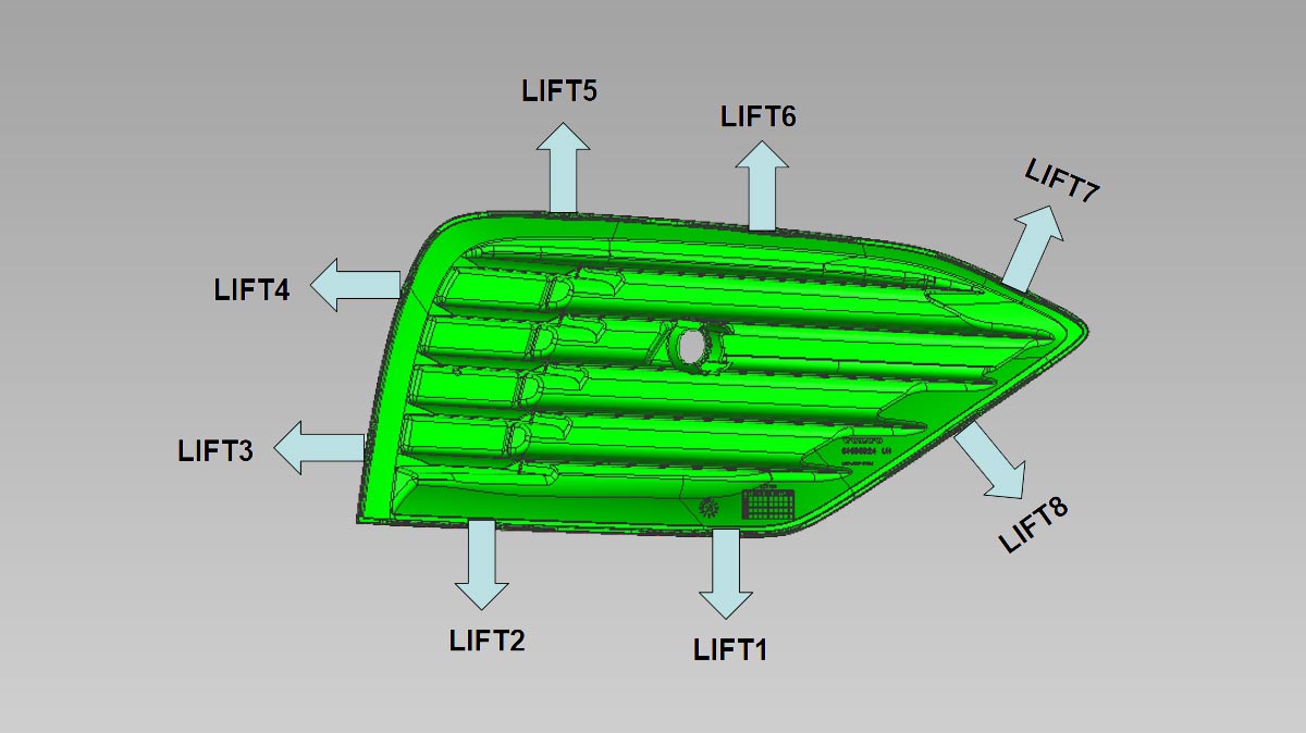
QuestionCan the part leave the tool without damage, drag or an unnecessary mechanism?
Engineering actionConfirm pull direction, draft, texture allowance, shutoffs, slides/lifters and acceptable witness areas.
ValidationReview ejection marks, surface damage and feature integrity during trials.
QuestionWill filling behavior place vestige, air traps or weld lines in a functionally and cosmetically acceptable area?
Engineering actionSelect gate location/type and venting around resin behavior, flow length, visible zones and load-bearing interfaces.
ValidationUse trial parts and, when scoped, flow analysis or process evidence to approve the result.
QuestionWhich dimensions control fit or function, and in what material/measurement condition?
Engineering actionSeparate CTQs from noncritical dimensions; review datum strategy, shrinkage, fiber orientation, cooling, cavity layout and conditioning.
ValidationMeasure against the agreed drawing, method, fixture, sampling plan and part condition; avoid blanket molded-part tolerance claims.
The physical process
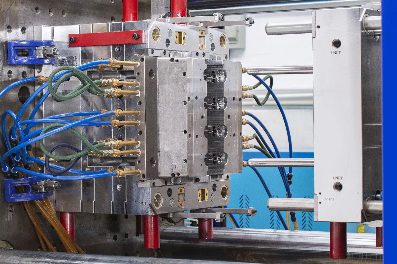
Resin preparation happens before the press cycle. The released material is stored and dried as the grade requires, then fed to the machine. Inside the cycle, controlled filling, packing, cooling and ejection turn one shot into parts that can be checked against the approved baseline.
Confirm material identity, color or additives and the grade-specific storage and drying condition before molding.
Plasticized resin enters the cavity through the runner and gate; speed, pressure, venting and material condition influence complete filling, surface response and weld-line location.
Pressure continues while the gate remains effective to compensate for material contraction. The balance affects weight, sink, flash, stress and dimensions.
The part remains in the closed mold until it has enough stability for release. Resin, wall sections, cooling layout and mold temperature shape cycle time and warpage.
The tool opens and the part is released without unacceptable drag, deformation or ejector marking; handling then protects the approved surfaces and features.
Project route
The mold enables production, but the control path is organized around the accepted part. Decisions and evidence move forward in stages so geometry, material, appearance and quality requirements are not silently changed between trial and repeat orders.
Review CAD/drawing, exact or target resin grade, forecast and release pattern, CTQs, appearance, end use, packaging, destination and required records.
Stage output: Defined assumptions, included scope, open risks, quotation structure and a proposed validation route.
Resolve feature, tooling, material, cavity, machine-fit and acceptance decisions; use Moldflow when required by the project.
Stage output: Approved engineering direction and controlled inputs for tool manufacture.
Build the production tool, mold first trial parts on suitable equipment and record issues against the drawing and acceptance plan.
Stage output: Trial samples and scoped measurement/process evidence for review.
Address agreed findings, re-trial as needed and confirm dimensions, appearance and functional checks within the project scope.
Stage output: Approved sample state and production-release conditions.
Run released material and controls, perform scoped first-piece/in-process/outgoing checks, identify batches and pack to the agreed requirement.
Stage output: Accepted production lots with the records and traceability specified for the order.
Acceptance plan
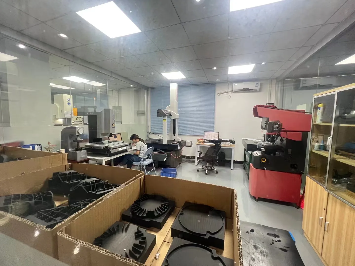
A useful quality plan states what will be checked, how, when and against which approved reference. WOKE Molds runs first-piece, in-process, appearance, CTQ, CMM, sampling and outgoing inspection with batch traceability as required by the project.
Identify functional dimensions, datums, gauges or CMM method, sampling, conditioning/measurement state and acceptance criteria on the controlled drawing.
Mark visible zones and agree color, gloss, texture, gate vestige and defect vocabulary under defined viewing conditions; use approved references or golden samples where appropriate.
Define mating parts, fastening, sealing, torque, pull-out, movement or other application checks that are actually required and feasible within scope.
Set first-piece, in-process and outgoing checkpoints, sampling, lot identity, exception handling and the records that accompany or remain traceable to the shipment.
Quote economics
A useful comparison separates one-time tooling and validation work from the recurring cost of accepted parts. Unit price is influenced by resin and additives, part and runner weight, cycle and cavity plan, labor or automation, scrap risk, inspection, packaging and release quantity—not by resin price or press tonnage alone.
Tooling and specified components, engineering after kickoff, trials/corrections, sample and validation work, and agreed initial records.
Released resin/grade, molding route, cycle/cavity assumptions, required handling, inspection, packaging and order quantity.
Lifecycle responsibilitiesTool ownership, use, storage, maintenance and any agreed transfer arrangements; change requests; revalidation; material or color changes; replacement wear items; and repeat-order assumptions.
Delivery scopeShipment destination, packing, release schedule and EXW, FOB or DDP terms as agreed for the project.
More cavities may spread cycle and labor across more parts, but only when demand, fill/cooling balance, projected area, shot size, machine fit, maintenance and cavity-level quality support the investment. The lowest tooling cost and the lowest cost per accepted part are not always the same route.
Comparing suppliers? Read how contract injection molding works and how to approach injection molding in China. Need a mold for your own plant? Explore Injection Mold Manufacturing →
Start with the controlled files and requirements you already have. Open items can be identified during review; the goal is to avoid a low-confidence quote built on silent assumptions.
Practical answers
This page is for recurring supply of drawing-based injection molded parts. Tooling, trials and maintenance are managed as enabling parts of that production program. If your purchased deliverable is a mold to run elsewhere, use the separate Injection Mold Manufacturing service.
Achievable tolerance depends on exact resin, geometry, shrinkage and warpage, tool/cavity layout, datums, process, conditioning and measurement method. Mark the functional CTQs; achievable limits and the inspection method are then confirmed through DFM and trial evidence.
Identify appearance zones and define color, gloss, texture, gate vestige and permitted defect conditions under an agreed inspection method. Approved samples or references can be used where appropriate so later lots are judged against a shared baseline rather than words such as “perfect.”
PP, ABS, PC, PA, POM, PBT, TPE, PC/ABS, PMMA, TPU, PPS, PEEK, LCP and PPA, including glass-, carbon-filled and flame-retardant grades, may be evaluated. The exact grade is confirmed against the part, tool, press conditions and required performance.
The project can scope FAI/full dimensional, CMM, material/COA, trial and inspection reports, PPAP, control plan, PFMEA, process flow, COC or 8D where relevant. Define the required format, submission timing and responsibility before quotation or release so the records match the approval plan.
Order quantity and production schedule are reviewed from tool readiness, resin availability, setup and validation, release quantity, inspection, capacity, packaging and shipping. The quotation aligns these factors with your forecast and delivery plan.
List every required downstream operation, purchased component, test and packaging step in the inquiry. We review the scope and confirm which operations we perform in-house, the acceptance checks and the responsibilities for the project.
Send a controlled revision and identify the affected function, material, appearance or interface. The impact on tooling, samples, inspection, stock and revalidation is reviewed before the changed part becomes the production baseline.
Start with your controlled files
Share the part, material direction, forecast and acceptance priorities you already know. We will review the scope, identify open engineering questions and respond with the next information needed for a production quotation.