
Overmold Tooling: Substrate Location, Shutoffs and Flash
Overmold tooling is the mold set that molds a second material over an existing part, called the substrate. The substrate may be a rigid plastic part, a metal insert or a cable. The overmold tool must hold the substrate in exactly the right place, seal against it so the second material does not flash, and let the two materials bond or lock together.
Most overmolding defects come from the tool, not the materials. For example, a substrate that sits 0.1 mm low in the cavity can leave a thin flash of TPE across a visible edge. Likewise, a shutoff that crushes a soft substrate can mark it on every part. In this guide, we explain overmold tooling: substrate location, shutoff design, flash control, venting, bonding and trials. For the process choice itself, see our guide to two-shot molding vs overmolding.
Overmold tooling consists of a substrate tool, which makes the first part, and an overmold tool, which locates that part and molds a second material over it. The overmold tool must locate the substrate on datums that match the substrate tool, seal against it with a controlled interference (typically about 0.05–0.1 mm on rigid substrates), and vent the second material at the end of fill. Flash is controlled by substrate tolerances, shutoff design, injection pressure and clamping. Bonding depends on material pairing and is often supported by mechanical locks.
In short: locate the substrate precisely, seal it with a controlled shutoff, and design both tools together.
Key points:
- Location: the substrate must sit on fixed datums.
- Shutoff: controlled interference prevents flash without crushing.
- Two tools, one design: substrate and overmold tools must match.
What Is Overmold Tooling?
Overmold tooling is the set of molds used to make an overmolded part. In a classic overmolding process, there are two tools:
- Substrate tool: molds the first, usually rigid, part.
- Overmold tool: holds the substrate and molds the second material over it.
The second material is often a TPE or TPU for grip, sealing or soft touch. However, it can also be a rigid plastic over a metal insert. In two-shot molding, both steps happen in one machine with a rotating or transfer mold. Our overmolding molds page shows typical tool designs.
Key Takeaway: Design the substrate and overmold tools as one project. Their datums and tolerances must match.
How Should the Substrate Be Located in Overmold Tooling?
The substrate should be located in overmold tooling on datum features that are also controlled in the substrate tool. Good location keeps the overmold thickness even and the shutoff consistent.
Location methods:
- Datum pins in holes molded into the substrate
- Pockets or nests that match the substrate outline
- Ribs or bosses that rest on hard stops
- Vacuum or magnets for thin or metal substrates
- Spring-loaded pins for parts with small size variation
For example, a handle substrate located by two holes and a flat face sits repeatably every cycle. In contrast, one located only by its outline may shift under injection pressure, so the overmold becomes thinner on one side. Our guide to insert molding design guidelines explains similar location rules for metal inserts.
Key Takeaway: Locate the substrate on the same datums used to inspect it. Then variation is predictable.
How Do You Design Shutoffs in Overmold Tooling?
You design shutoffs in overmold tooling so the steel presses slightly into the substrate along a defined line, sealing it without crushing or marking it.
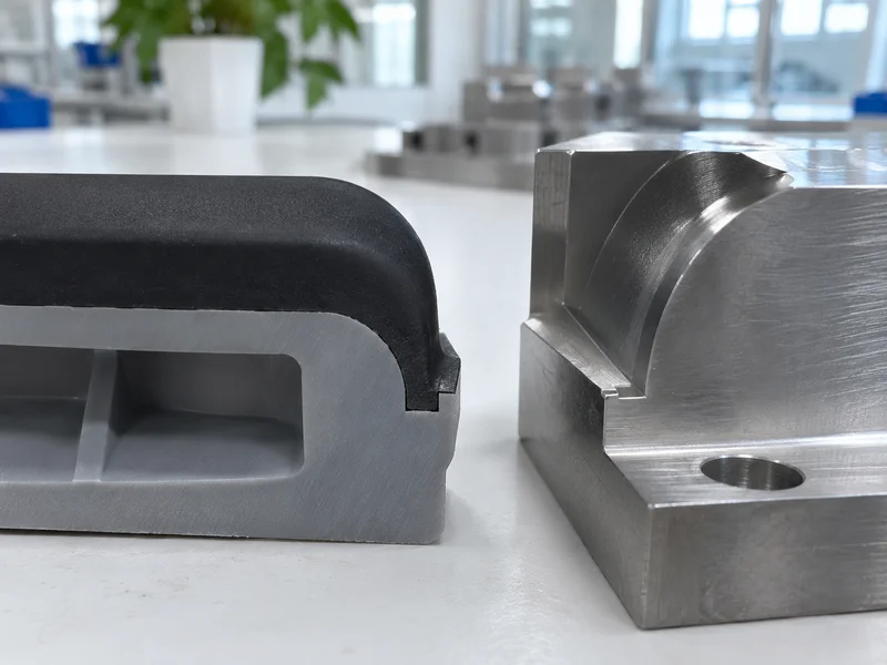
Shutoff guidelines:
- Interference: typically about 0.05–0.1 mm on rigid substrates, adjusted per material
- Shutoff width: narrow enough to seal, wide enough to avoid cutting
- Location: on a step or groove, not on a flat cosmetic face
- Hardened steel: shutoff edges wear, so they need hardness
- Substrate tolerance: tight at the shutoff line
For example, a TPE grip ending on a flat face of a PC/ABS housing often shows flash. Moving the shutoff into a small groove gives a clean edge that hides minor variation. Our guide to parting line injection molding explains shutoff principles in more detail.
Key Takeaway: End overmolds in a groove or step, never on a flat surface. Geometry does most of the flash control.
How Do You Control Flash in Overmolding?
You control flash in overmolding by combining good substrate tolerances, correct shutoffs and suitable process settings.
Main causes and fixes:
- Substrate too small at the shutoff: tighten tolerances on the substrate tool
- Substrate shifting: add datum pins or vacuum
- Injection pressure too high: reduce pressure and speed near end of fill
- Low-viscosity overmold material: use tighter shutoffs and lower melt temperature
- Worn shutoff edges: repair or replace inserts
For example, flash that appears only on parts from one substrate cavity points to a dimensional difference in that cavity. Measuring substrates by cavity finds it quickly. Our quality control and inspection process supports per-cavity measurement when required.
Key Takeaway: Trace flash back to substrate cavity numbers. Many “overmold” problems start in the substrate tool.
How Should Overmold Tooling Be Vented?
Overmold tooling should be vented at the last points to fill, where the second material traps air against the substrate.
Venting points:
- End of flow of the overmold material
- Around ribs and pockets where air can be trapped
- At the substrate interface, using vent grooves in the steel
- Through ejector pins or vent inserts in deep areas
For example, a soft-touch TPE grip can show burn marks or poor fill at the end of a groove. Adding a vent at that point fixes it. Because TPEs flash easily, vent depths must be shallow. Our guide to injection mold venting gives typical vent depths by material.
Key Takeaway: Vent the overmold side carefully. Too deep causes flash; too shallow causes burns.
How Do You Ensure Bonding in Overmolded Parts?
You ensure bonding in overmolded parts by choosing compatible materials and adding mechanical locks where bond strength is critical.
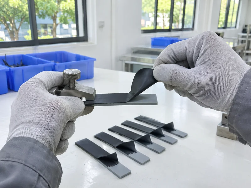
Bonding factors:
- Material compatibility: for example, TPE grades designed for PC, ABS or PA
- Substrate surface: clean, dry and free of mold release
- Substrate temperature: warmer substrates bond better
- Overmold melt temperature: high enough to fuse the interface
- Mechanical locks: holes, undercuts and grooves for critical areas
For example, a TPE seal on a PP housing may peel unless the TPE grade is made for PP. Through-holes in the substrate add a mechanical lock that holds even if the chemical bond weakens. Material compatibility information is published by resin suppliers, and adhesion test methods are described by standards bodies such as ASTM International.
Key Takeaway: Do not rely on chemical bonding alone for safety-critical joints. Add mechanical locks.
What Should Overmold Tooling Trials Check?
Overmold tooling trials should check substrate fit, flash, bonding, appearance and dimensions on real parts from both tools.
Trial checks:
- Substrate fit in every overmold cavity
- Flash at all shutoff lines
- Bond strength, using a peel or pull test
- Appearance of grip, color and gloss
- Dimensions of the finished part
- Process window, including substrate temperature if preheated
For example, the first trial may show good bonding but slight flash at one corner. Adjusting the shutoff interference and retesting at T2 is normal. Our standard mold quote includes up to 3 mold trials and 10-shot samples. Our overmolding service covers production after tool approval.
Key Takeaway: Test bonding on parts from every substrate and overmold cavity combination, not only one.
FAQ
- Q: What is overmold tooling?
- The molds used to make an overmolded part: a substrate tool and an overmold tool that molds a second material over the substrate.
- Q: How do you prevent flash in overmolding?
- Use tight substrate tolerances, accurate location, controlled shutoff interference and suitable injection settings.
- Q: What shutoff interference is used in overmold tools?
- Typically about 0.05–0.1 mm on rigid substrates, adjusted to the materials.
- Q: Why does an overmold peel off the substrate?
- Usually because of incompatible materials, a cold or contaminated substrate, or no mechanical locks.
- Q: What is the difference between overmolding and two-shot molding?
- Overmolding usually uses separate tools and moves the substrate between them; two-shot molding does both shots in one machine and mold.
Conclusion
Overmold tooling succeeds when the substrate is located precisely, sealed by a well-designed shutoff and bonded with the right materials and locks. Design both tools together and check flash and bonding at every trial. To review an overmolded part, send your 3D model and 2D drawing to our engineers.