
Submarine Gate: Angles, Sizes and Gate Vestige
A submarine gate, also called a tunnel gate, enters the part below the parting line through an angled tunnel in the mold. When the mold opens and the part is ejected, the gate is sheared off automatically. As a result, parts drop free of the runner without manual trimming, which makes submarine gates popular for small, high-volume parts.
The automatic degating only works when the gate is designed for the material and the ejection path. For example, a submarine gate that is too steep can break off inside the tunnel and block the next shot. A gate in a brittle, glass-filled resin may snap unevenly and leave a raised vestige. In this guide, we explain submarine gate design: degating path, angles and sizes, gate vestige, material limits and tool access. For the full range of gates, see our guide to injection molding gate types.
A submarine gate is a cold runner gate machined as a tapered tunnel that enters the part side wall below the parting line, usually at about 30–45° to the parting plane with a cone angle of about 15–30°. On ejection, the part and runner are pulled apart and the gate shears at the part surface, leaving a small round vestige. It needs a flexible enough runner, an ejector pin near the runner to bend it out of the tunnel, and a resin that shears cleanly. Brittle or highly filled resins and very large gates are less suitable.
In short: design the submarine gate angle, size and runner ejection together, so the gate shears cleanly every shot.
Key points:
- Automatic degating: parts separate from the runner at ejection.
- Angles: entry angle and cone angle decide shear and pull-out.
- Material: flexible resins work best; brittle ones can break in the tunnel.
What Is a Submarine Gate?
A submarine gate is a small gate that reaches the part through a tunnel below the parting line. The runner sits on the parting plane, and the tunnel dives into the cavity side wall or into an ejector pin or rib.
Common variants:
- Standard submarine gate into the part side wall
- Gate into an ejector pin (the gate enters a cut on a pin, hidden on a non-cosmetic face)
- Curved or banana gate, which enters the part from below a cosmetic surface
- Gate into a rib or post to hide the vestige
For example, a small electrical connector housing is often gated with a submarine gate into a non-visible side, so thousands of parts drop into a box with no trimming. Our injection mold manufacturing projects use submarine gates where the part, resin and cosmetic needs allow.
Key Takeaway: Choose a submarine gate when automatic degating matters and the vestige can sit on a non-critical surface.
How Does the Submarine Gate Degating Path Work?
The submarine gate degating path works by pulling the part and runner in different directions as the mold opens and ejects. The tunnel edge acts as a knife that shears the gate.
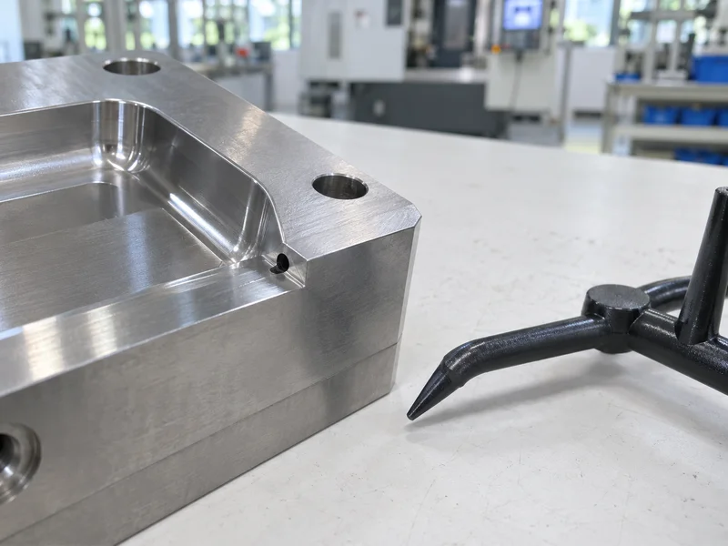
The sequence:
- Mold opens: the part stays on the core; the runner is held by a sprue puller or undercut.
- Gate shears: the tunnel edge cuts the gate at the part surface.
- Runner ejects: ejector pins under the runner bend the tunnel plug out.
- Part ejects: the part falls free, separate from the runner.
For example, if the runner ejector pin is too far from the tunnel, the plug may not bend out and stays stuck. Then the next shot fills a blocked gate, causing a short shot. Our guide to ejector pin marks explains ejection balance.
Key Takeaway: Place a runner ejector pin close to every submarine gate. Stuck plugs are the most common failure.
What Angles and Sizes Work for a Submarine Gate?
The angles and sizes that work for a submarine gate depend on the resin, part wall and shot size, but typical values give a good start.
| Feature (typical) | Guideline |
|---|---|
| Entry angle to parting plane | about 30–45° |
| Tunnel cone angle | about 15–30° |
| Gate tip diameter | about 0.5–2.0 mm, often 30–60% of wall thickness |
| Distance below parting line | enough steel for a strong shear edge |
| Runner flexibility | runner must bend out of the tunnel |
Steeper or narrower tunnels make the plug harder to pull out. Larger tips leave a bigger vestige and need more force to shear. For example, a 1 mm gate tip suits a 2 mm wall in PP well, while a stiff PC part may need a slightly larger tip and a gentler angle. Simulation helps check gate size and freeze time; our guide to mold flow analysis explains it.
Key Takeaway: Start with standard angles, then confirm gate size by simulation and the first trial.
What Gate Vestige Should You Expect From a Submarine Gate?
You should expect a small, round gate vestige from a submarine gate, roughly the size of the gate tip, slightly raised or flush with the surface.
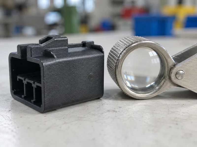
Factors that change the vestige:
- Gate tip size: bigger gates leave bigger marks.
- Resin toughness: tough resins may stretch and leave a small tail.
- Mold temperature: a hot gate area can drag or string.
- Shear edge condition: a worn tunnel edge leaves ragged marks.
For example, a TPE or soft PP part may leave a small stretched tail at the gate, while a stiff ABS part shears cleanly. Agree an acceptable vestige height on the drawing, such as “gate vestige ≤ 0.2 mm, non-cosmetic face”. Our guide to injection molding tolerances covers how to state such limits.
Key Takeaway: Put the gate location and maximum vestige on the drawing. It avoids disputes at sample approval.
Which Materials Are Not Ideal for Tunnel Gating?
Materials that are brittle, highly filled or very stiff are not ideal for a submarine gate, because the runner may snap in the tunnel instead of bending out.
Use extra care with:
- High glass-fiber grades, such as PA66-GF50
- Brittle resins, such as some PS or PMMA grades
- Very stiff resins with low elongation
- Shear-sensitive or degradable resins, due to high shear at small gates
For example, a 30% glass-filled nylon may work with a larger gate and a curved tunnel, but a 50% glass grade often needs an edge gate or a hot runner instead. Our guide to hot runner vs cold runner molds compares alternatives.
Key Takeaway: Tell the toolmaker the exact resin and filler level. It decides whether a submarine gate is safe.
How Do You Plan Tool Access for Gate Inserts?
You plan tool access for submarine gates by making the tunnel easy to machine, inspect and repair, because the shear edge wears over time.
Good practice:
- Gate inserts: put the tunnel in a replaceable insert where possible.
- EDM or machining access: the tunnel must be reachable for re-cutting.
- Polish: the tunnel should be polished in the draw direction to aid pull-out.
- Hardness: hardened steel at the shear edge, especially for filled resins.
- Spare inserts: for high-volume molds, keep spare gate inserts.
For example, a gate insert that can be swapped in an hour keeps production running when the shear edge wears. Our guide to mold maintenance explains planned checks. Standard test specimens are molded with defined gates under standards from ISO, such as ISO 294, which shows how much gate design matters for consistent parts.
Key Takeaway: Put submarine gates in replaceable inserts on high-volume molds. Gate wear is predictable.
FAQ
- Q: What is a submarine gate in injection molding?
- A tunnel gate that enters the part below the parting line and shears off automatically during ejection.
- Q: What is the typical angle of a submarine gate?
- The entry angle is usually about 30–45° to the parting plane, with a cone angle of about 15–30°.
- Q: What are the advantages of a submarine gate?
- Automatic degating, a small vestige and no manual trimming.
- Q: Why does a submarine gate get stuck?
- Usually because the runner is too stiff, the tunnel is too steep or the runner ejector pin is too far away.
- Q: Can submarine gates be used with glass-filled plastics?
- Sometimes, with larger gates and gentler angles, but highly filled grades often need another gate type.
Conclusion
A submarine gate gives automatic degating and a small vestige when its angles, size, runner ejection and material are designed together. Plan the vestige location, check the resin and put the gate in a serviceable insert. To review gating for your part, send your 3D model and 2D drawing to our engineers.