
GD&T Profile Tolerance: Datums, Zones and Realistic Values
GD&T profile tolerance controls the shape of a curved or irregular surface or outline. Instead of dimensioning every point of a complex surface with ± tolerances, profile tolerance defines a uniform zone around the true profile from the CAD model. For machined surfaces such as cam faces, sealing contours, freeform housings and mating surfaces, it is often the clearest and most complete way to state what is required.
It is also one of the most misused callouts. For example, a profile tolerance without datums controls only form, so a perfectly shaped surface can still be in the wrong place. Conversely, a tight profile tied to datums on a large freeform part can make machining and inspection very expensive. In this guide, we explain GD&T profile tolerance on machined surfaces: profile of a surface vs a line, datums, zone distribution, typical values, machining strategy and CMM inspection. For hole patterns, see our guide to GD&T position tolerance.
GD&T profile tolerance defines a uniform-width zone, normally equally disposed around the true profile defined by basic dimensions or the CAD model. Profile of a surface controls an entire surface in 3D; profile of a line controls 2D cross-sections. Without datums, profile controls only form; with datums, it also controls size, orientation and location. Unequal zones can be specified with the U modifier (ASME) or UZ (ISO). Machined surfaces are typically held with 5-axis or 3-axis finishing strategies and verified by CMM scanning against the model.
In short: profile tolerance controls complex shapes with one zone; datums decide whether it also controls location.
Key points:
- Surface vs line: 3D surface or 2D sections.
- Datums: add location and orientation control.
- Inspection: CMM scanning against the CAD model.
What Is GD&T Profile Tolerance?
GD&T profile tolerance is a geometric control that limits how far a surface or outline may deviate from its true profile. The true profile comes from basic dimensions on the drawing or from the 3D model.
Two types:
- Profile of a surface: a 3D zone over the whole surface.
- Profile of a line: a 2D zone in each cross-section.
For example, a curved sealing face on a housing may carry “profile of a surface 0.1 A B C”, meaning every point must lie within a 0.1 mm wide zone located from datums A, B and C. The rules are defined in standards from ISO, including ISO 1101, and in ASME Y14.5.
Key Takeaway: Use profile when a shape is too complex for ± dimensions.
How Do Datums Change a GD&T Profile Tolerance?
Datums change a profile tolerance by deciding what the zone controls.
| Profile callout | What it controls |
|---|---|
| Without datums | Form only (shape), floating in space |
| With primary datum | Form and orientation to that datum |
| With full datum reference frame | Form, orientation, location and size |
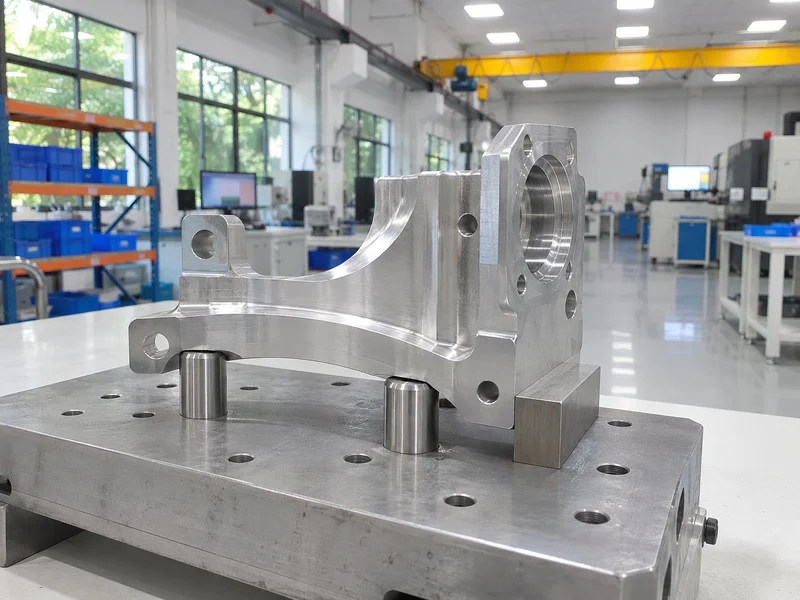
For example, profile without datums on a cam surface checks only that the curve has the right shape. If the cam must also be in the right place relative to the shaft bore, the profile needs datums. Our guide to CMM measurement explains how datums are set up.
Key Takeaway: Decide whether the shape alone matters, or its location too. Then choose datums.
What Is the Difference Between Profile of a Surface and Profile of a Line?
The difference between profile of a surface and profile of a line is the dimension of the zone: a surface zone covers the whole 3D surface, while a line zone applies to each 2D section separately.
- Profile of a surface: used for freeform faces, sealing surfaces, molded-to-machined interfaces.
- Profile of a line: used for extrusions, airfoil sections and surfaces where each section matters but variation along the length is allowed.
For example, a long extruded aluminum rail may use profile of a line, so each cross-section is correct, with straightness controlled separately. A machined manifold sealing face would use profile of a surface.
Key Takeaway: Use profile of a surface by default; use profile of a line when only sections matter.
How Are Profile Tolerance Zones Distributed?
Profile tolerance zones are distributed equally around the true profile by default, but they can be shifted to one side.
Options:
- Equal bilateral (default): a 0.2 mm zone is ±0.1 mm.
- Unequal (U or UZ modifier): for example 0.2 mm with 0.15 mm outside and 0.05 mm inside.
- Unilateral: all on one side, such as “material may only be added” or “only removed”.
For example, a surface that mates against a gasket might allow more material outside than inside, so the gasket always gets compression. Unequal zones make that requirement explicit.
Key Takeaway: Use unequal zones when the function favors one direction.
What Profile Tolerance Values Are Realistic on Machined Surfaces?
Realistic profile tolerance values on machined surfaces depend on part size, material, machining method and inspection, not only on machine capability.
Typical guidance:
- Small to medium aluminum parts, finished on 5-axis: about 0.05–0.1 mm is common.
- Large parts: wider, because of setup and thermal effects.
- Thin-walled or plastic parts: wider, because of flexibility.
- Very tight values: possible on small features with fine finishing and controlled temperature.
Machine capability is not finished-part tolerance. For example, a 5-axis machine may position to a few microns, but a 300 mm thin aluminum housing can still distort more than that when released. Our Dongguan factory includes a Makino 5-axis machining center, and finished tolerances are controlled per drawing.
Key Takeaway: Ask for a manufacturability review before freezing tight profile values on large or thin parts.
How Are Profile-Toleranced Surfaces Machined?
Profile-toleranced surfaces are machined with finishing strategies that follow the surface accurately and keep tool deflection low.
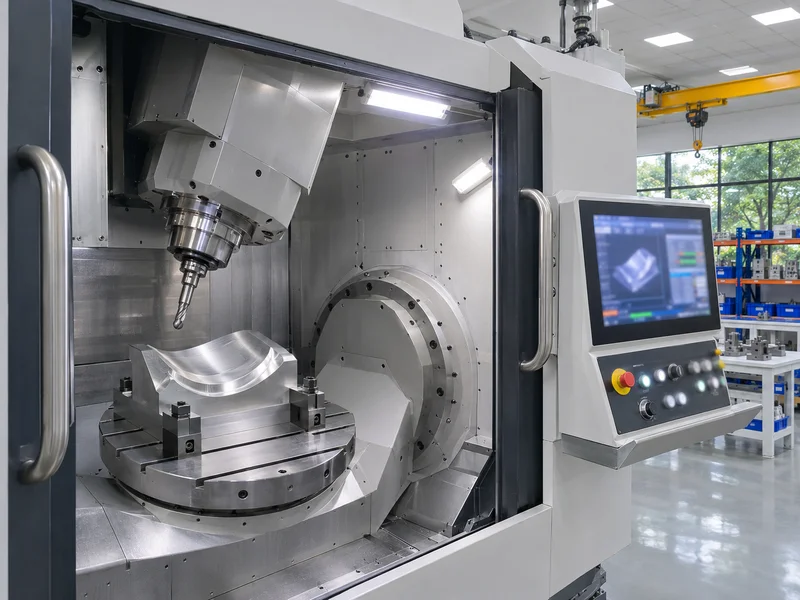
Machining practice:
- 5-axis finishing to keep the tool normal to the surface
- Small step-overs with ball or bull-nose cutters
- Semi-finish then finish to leave even stock
- Stable workholding on datums
- Temperature control for tight tolerances
For example, a freeform aluminum cover may be roughed on 3 axes and finished on 5 axes, so the cutter angle stays constant and the surface stays within profile. Our CNC milling service covers 3- and 5-axis machining, and our guide to 5-axis milling explains tool access.
Key Takeaway: Plan finishing passes around the profile requirement, not just the shape.
How Is GD&T Profile Tolerance Inspected?
GD&T profile tolerance is inspected by measuring many points on the surface and comparing them to the CAD model within the datum frame.
Inspection methods:
- CMM scanning with a touch probe along the surface
- Point sampling at defined locations for simpler parts
- Optical or laser scanning for large freeform surfaces
- Color deviation maps to show where the surface is high or low
For example, a CMM report may show a color map with all points within ±0.05 mm except one area at +0.07 mm, telling the machinist exactly where to adjust. Our quality control and inspection process uses a CMM with a 1,200 × 1,000 × 800 mm range, and reports are supplied on request.
Key Takeaway: Ask for a deviation map with profile results. It shows where to fix, not only pass or fail.
FAQ
- Q: What is profile tolerance in GD&T?
- A uniform zone around the true profile of a surface or line, defined from basic dimensions or the CAD model.
- Q: What is the difference between profile of a surface and profile of a line?
- Profile of a surface controls the whole 3D surface; profile of a line controls each 2D cross-section.
- Q: Does profile tolerance need datums?
- Not always. Without datums it controls form only; with datums it also controls orientation, location and size.
- Q: What does the U or UZ modifier mean?
- It shifts the profile zone unequally to one side of the true profile.
- Q: How is profile tolerance measured?
- Usually by CMM scanning against the CAD model in the datum frame.
Conclusion
GD&T profile tolerance controls complex machined surfaces with a single zone, and datums decide whether it also controls location. Choose surface or line profile, set realistic values, machine with suitable finishing strategies and inspect with CMM scans. To review a profile-toleranced part, send your 3D model and 2D drawing to our engineers.