
Jetting Injection Molding Defects: Causes and Fixes
Jetting injection molding defects appear as a snake-like or worm-like flow mark on the part surface, usually starting at the gate. It happens when melt shoots through the gate into an open cavity as a free jet instead of spreading out against the mold wall. The jet cools before the rest of the melt surrounds it, leaving a visible, often weak, wavy line.
Jetting is mainly a gate and initial-fill problem, so it is best fixed in the tool and the first part of the injection profile. For example, a small edge gate that shoots straight into a thick, open area of a part is a classic jetting setup. Raising temperature may soften the mark, but moving the gate so the melt hits a wall usually removes it completely. In this guide, we explain how to trace jetting injection molding marks back to the gate and initial fill, and how to fix them in design, tooling and process. For gate types, see our guide to injection molding gate types.
Jetting injection molding defects occur when melt enters a cavity through a small gate at high velocity into an open space, forming a free jet that folds and cools before being surrounded by later melt. It appears as a wavy, snake-like mark starting at the gate and can weaken the part. Causes are gates that face an open area, gates too small for the wall thickness, high initial injection speed and low melt or mold temperature. Fixes include gating against a wall or pin (impingement), using fan or tab gates, increasing gate size, profiling a slow initial injection speed and raising melt or mold temperature.
In short: jetting starts at the gate; fix it by directing the flow against a wall, sizing the gate correctly and slowing the first part of fill.
Key points:
- Cause: free jet from a small gate into open space.
- Tool fix: impingement, fan or tab gate, larger gate.
- Process fix: slow initial injection speed.
What Do Jetting Injection Molding Marks Look Like?
Jetting injection molding marks look like a wavy, folded line, similar to a snake or a ribbon, that starts at the gate and runs into the part.
Typical features:
- Starts at the gate
- Wavy or coiled pattern
- Visible on glossy and transparent parts
- May show as a matte or different-gloss line
- Sometimes a weak line that can crack under load
For example, a clear PC lens with a thin edge gate may show a coiled line just inside the gate. That line is the frozen jet. Our guide to clear plastic injection molding explains why gating is critical for clear parts.
Key Takeaway: If the mark starts at the gate and wiggles, suspect jetting.
Why Does Jetting Happen?
Jetting happens because the melt leaves the gate faster than it can spread, and there is no nearby wall to slow and spread it.
Contributing conditions:
- Gate faces an open, thick area with no wall in front
- Gate is much thinner than the wall it feeds
- High injection speed at the start of fill
- Low melt or mold temperature, making the jet freeze quickly
- High-viscosity materials that resist spreading
For example, a 0.8 mm gate feeding a 4 mm wall almost always jets unless the flow hits a wall first. In contrast, a gate feeding a thin wall of similar thickness rarely jets. Our guide to mold flow analysis shows how simulation can predict this.
Key Takeaway: Compare gate thickness to wall thickness. A big step down invites jetting.
How Do You Trace Jetting Back to the Gate?
You trace jetting back to the gate by running short shots and examining how the melt first enters the cavity.
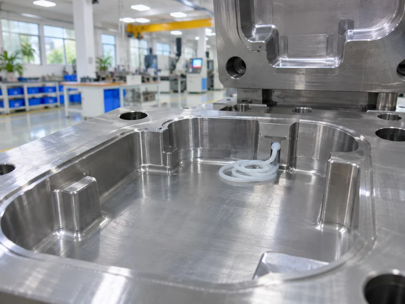
Investigation steps:
- Run very short shots that fill only a few percent of the cavity.
- Look at the first melt entering: a rope or coil means jetting.
- Compare gate size and wall thickness.
- Check gate direction: does it face a wall or an open space?
- Reduce initial speed and see whether the rope disappears.
For example, a very short shot that shows a thin coiled rope lying in the cavity confirms jetting, while a short shot showing a smooth, spreading flow front rules it out. Our quality control and inspection process records short-shot studies during trials when needed.
Key Takeaway: A very short shot shows jetting clearly. Use it before changing the tool.
How Do You Fix Jetting Injection Molding Defects in the Tool?
You fix jetting in the tool by changing the gate so the melt spreads immediately as it enters.
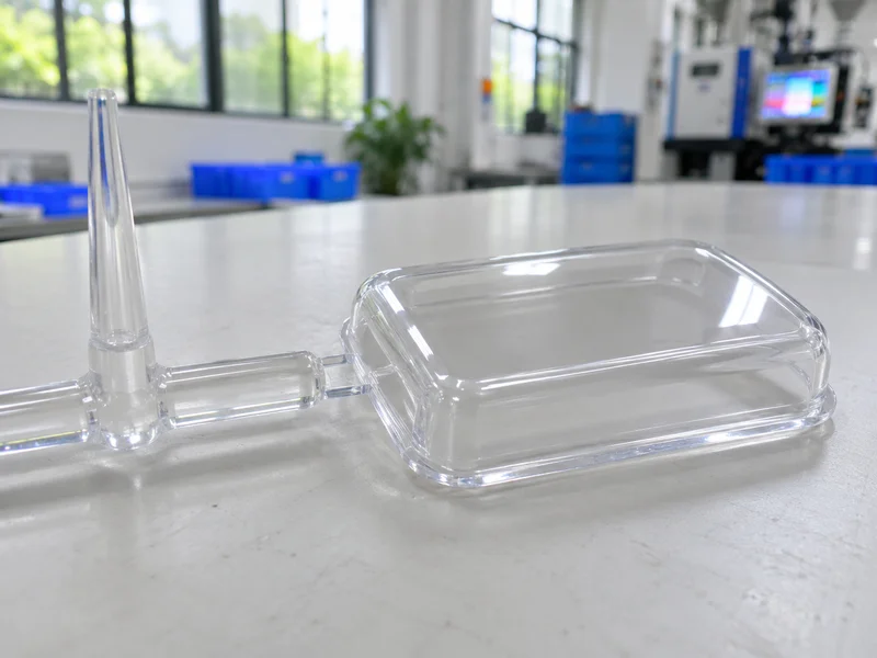
Tool fixes:
- Impingement gating: aim the gate at a wall, pin or rib close to the gate.
- Fan gate: spreads melt across a wider entry.
- Tab gate: melt enters a tab first, then the part.
- Larger gate: reduces entry velocity.
- Gate location: move into a thinner area or toward a wall.
- Overlap gate: gate onto the part face so melt hits the opposite wall.
For example, changing a straight edge gate into a tab gate can eliminate jetting without changing the process, because the jet forms in the tab, which is later removed. Our injection mold manufacturing team reviews gate design before steel is cut.
Key Takeaway: Fix jetting at the gate. Tool changes give a permanent solution.
How Do You Reduce Jetting Through the Process?
You reduce jetting through the process by slowing the first part of injection and keeping the melt hot enough to spread.
Process adjustments:
- Profile injection speed: slow for the first few percent of fill, then faster.
- Raise melt temperature within the resin’s range.
- Raise mold temperature to slow freezing of the jet surface.
- Check gate temperature on hot runner systems.
For example, starting injection at 20% speed until the melt passes the gate area, then increasing to normal speed, often removes jetting while keeping cycle time. However, too slow a start can cause other defects such as flow marks. Our guide to decoupled molding explains speed profiles.
Key Takeaway: Use a slow-start speed profile as a quick fix, then plan a gate change if the margin is small.
How Do You Prevent Jetting Injection Molding Defects in New Parts?
You prevent jetting in new parts by reviewing gate location and size during design and checking them with simulation.
Prevention checklist:
- Gate into a thin section or toward a wall
- Gate thickness close to the wall thickness, often about 50–80%
- Avoid gates facing large open areas
- Use fan or tab gates for cosmetic and clear parts
- Simulate the initial fill for critical parts
For example, a cosmetic black housing with a large flat face is best gated at an edge where the melt meets a rib immediately. Material behavior used in simulation is measured with methods from bodies such as ISO.
Key Takeaway: Treat gate design as part of the cosmetic specification for glossy and clear parts.
FAQ
- Q: What is jetting in injection molding?
- A snake-like flow mark caused by melt shooting through the gate as a free jet before spreading against the mold wall.
- Q: What causes jetting?
- Small gates facing open areas, high initial injection speed and low melt or mold temperature.
- Q: How do you fix jetting?
- Gate against a wall or pin, use a fan or tab gate, enlarge the gate or slow the initial injection speed.
- Q: Does jetting weaken parts?
- It can. The jet surface cools and may not bond fully, creating a weak line.
- Q: Is jetting the same as a flow mark?
- Jetting is one type of flow mark, specifically starting at the gate with a wavy pattern.
Conclusion
Jetting injection molding defects start at the gate, so the lasting fix is in gate design: direct the flow against a wall, size the gate correctly and use fan or tab gates for cosmetic parts. A slow-start speed profile helps in the short term. To review gating for your part, send your 3D model and 2D drawing to our engineers.