
Simultaneous 5-Axis Machining: When You Need It
Simultaneous 5-axis machining moves all five axes at once while the tool is cutting, so the cutter can follow a curved surface continuously with the best tool angle. It is used for impellers, turbine-style blades, freeform housings, mold inserts, medical-style implant shapes and ergonomic parts. Unlike 3+2 machining, where the part is tilted and then locked, simultaneous motion produces smooth, continuous surfaces with shorter tools.
The surface quality of a simultaneous 5-axis part depends on the CAM strategy, machine kinematics and verification, not only on the machine. For example, a freeform cover can show faint facets or witness lines if the toolpath tolerance is too coarse or the axes reverse direction abruptly. In this guide, we explain simultaneous 5-axis machining: how it differs from 3+2, when it is needed, what affects surface continuity, CAM and simulation, and how to verify the result. For an overview, see our guide to 5-axis milling.
Simultaneous 5-axis machining moves three linear axes and two rotary axes together during cutting, keeping the tool at a controlled angle to a curved surface. It is needed for continuous freeform surfaces, impeller blades, undercut curved walls and deep cavities where short tools must tilt. Surface continuity depends on toolpath tolerance, tool-axis smoothing, step-over, machine dynamics and rotary-axis accuracy. Verification uses simulation before cutting and CMM or optical scanning against the CAD model, with visual checks for facets and witness lines.
In short: use simultaneous 5-axis for continuous freeform surfaces, smooth the tool axis and verify against the model.
Key points:
- Continuous motion: all axes move during cutting.
- Surface quality: set by CAM tolerance and axis smoothing.
- Verification: simulation before, scanning after.
What Is Simultaneous 5-Axis Machining?
Simultaneous 5-axis machining is CNC milling in which X, Y, Z and two rotary axes move together while the tool cuts.
How it works:
- Linear axes move the tool through space.
- Rotary axes tilt and rotate the part or spindle.
- The control coordinates all five to keep the tool at the programmed angle.
- The tool follows the surface continuously.
For example, finishing a turbine-style blade requires the tool to wrap around the leading edge while tilting continuously. Fixed 3+2 positions would leave steps.
Key Takeaway: Simultaneous motion is about tool orientation during the cut, not only access.
How Does Simultaneous 5-Axis Machining Differ From 3+2 Machining?
Simultaneous 5-axis machining differs from 3+2 machining because the rotary axes move during cutting instead of being locked.
| Feature | 3+2 (positional) | Simultaneous 5-axis |
|---|---|---|
| Rotary axes during cut | Locked | Moving |
| Typical use | Multi-face prismatic parts | Freeform, blades, curved walls |
| Programming | Simpler | More complex |
| Surface | Very stable | Continuous on curves |
| Machine demands | Lower | Higher dynamics and accuracy |
For example, a valve body with holes on angled faces suits 3+2, while a freeform handle suits simultaneous motion. Our CNC milling service covers both 3+2 and simultaneous 5-axis work.
Key Takeaway: Use 3+2 where possible; use simultaneous motion where surfaces demand it.
When Is Simultaneous 5-Axis Machining Needed?
Simultaneous 5-axis machining is needed when a surface cannot be finished well with fixed tool angles.
Typical cases:
- Impellers and blades with twisted surfaces
- Freeform housings and covers
- Deep mold cavities where a short, tilted tool avoids chatter
- Undercut curved walls
- Swarf (flank) milling of ruled surfaces
- Ergonomic and medical-style shapes
For example, finishing a deep mold cavity wall with a tilted short tool gives better finish than a long tool held vertically. Our Dongguan factory includes a Makino 5-axis machining center for such work. Machine capability is not finished-part tolerance; finished tolerances depend on part, material and process.
Key Takeaway: Simultaneous motion is a surface-quality tool, not just a way to reach features.
What Affects Surface Continuity in Simultaneous 5-Axis Machining?
Surface continuity in simultaneous 5-axis machining is affected by toolpath tolerance, tool-axis smoothness, step-over and machine dynamics.
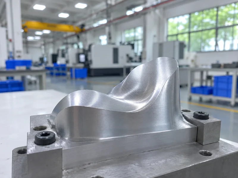
Factors:
- Toolpath tolerance: too coarse leaves facets.
- Tool-axis smoothing: abrupt changes leave marks.
- Step-over and scallop height: set surface roughness.
- Rotary-axis reversals: can leave witness lines.
- Machine dynamics: acceleration and look-ahead settings.
- Tool deflection on long or thin tools.
For example, a cover that shows faint lines where the B-axis reverses can be improved by smoothing tool-axis changes in CAM. Our guide to surface roughness Ra vs Rz explains roughness values.
Key Takeaway: Most visible defects on 5-axis surfaces come from CAM settings, not the machine.
How Do CAM and Simulation Support Simultaneous 5-Axis Machining?
CAM and simulation support simultaneous 5-axis machining by planning tool orientation and checking collisions before cutting.
Practice:
- CAM strategies: surface-normal, tilt-relative-to-path, swarf
- Tool-axis control: limits and smoothing
- Machine simulation with the real kinematics and fixture
- Collision checks for holder, spindle and fixture
- Post-processor matched to the machine
For example, a holder collision that appears only at one extreme rotary angle is found in simulation instead of on the machine. We program in Siemens NX CAM, with simulation used on complex multi-axis work. See our CNC machining services.
Key Takeaway: Simulate with the real machine model. Generic simulation misses collisions.
How Do You Verify a Simultaneous 5-Axis Machined Surface?
You verify a simultaneous 5-axis machined surface by comparing it with the CAD model and checking appearance.
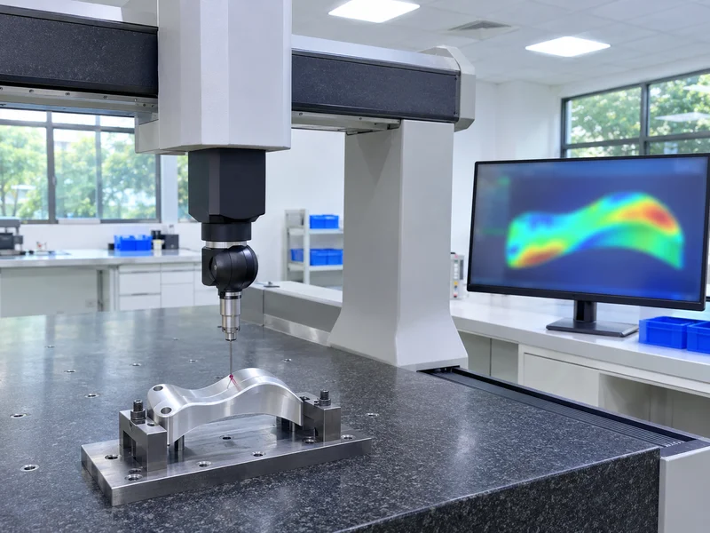
Verification methods:
- CMM scanning within the datum frame
- Optical or laser scanning for full-surface deviation maps
- Profile tolerance evaluation
- Roughness measurement on representative areas
- Visual inspection for facets and witness lines under defined light
For example, a deviation color map can show a slight high area near a blade tip, guiding a CAM correction. Test conditions for machining center accuracy are defined in ISO 10791 from ISO. Our guide to GD&T profile tolerance explains how surfaces are toleranced.
Key Takeaway: Ask for a deviation map, not just pass or fail, on freeform surfaces.
What Should You Provide When Quoting Simultaneous 5-Axis Parts?
You should provide information that lets the supplier plan the toolpaths and inspection.
Quote inputs:
- 3D model (STEP) as the surface master
- 2D drawing with datums and profile tolerances
- Surface finish requirements by area
- Cosmetic criteria for visible surfaces
- Material and stock form
- Quantity
For example, stating “profile 0.05 mm on blade surfaces, Ra 0.8 µm” lets the supplier choose step-over and inspection. Our quality control and inspection process supplies reports on request.
Key Takeaway: The 3D model is the master for freeform surfaces. Keep it consistent with the drawing.
FAQ
- Q: What is simultaneous 5-axis machining?
- Milling with all five axes moving together during cutting to follow curved surfaces.
- Q: How is it different from 3+2 machining?
- In 3+2, rotary axes are locked during cutting; in simultaneous machining they move.
- Q: When is simultaneous 5-axis needed?
- For freeform surfaces, blades, impellers, deep cavities and curved undercuts.
- Q: What causes facets on 5-axis surfaces?
- Coarse toolpath tolerance, abrupt tool-axis changes or rotary reversals.
- Q: How are 5-axis surfaces inspected?
- By CMM or optical scanning against the CAD model, plus roughness and visual checks.
Conclusion
Simultaneous 5-axis machining produces continuous freeform surfaces when CAM tolerance, tool-axis smoothing and machine dynamics are controlled, and when the result is verified against the model. Use it where surfaces demand it. To review a 5-axis part, send your 3D model and 2D drawing to our engineers.