
Thread Gauge: Go/No-Go Checks and Thread Classes
A thread gauge checks whether a machined thread will accept its mating part. The most common types are go/no-go thread plug gauges for internal threads and thread ring gauges for external threads. They test the thread’s functional size quickly and reliably on the shop floor and at incoming inspection, which a caliper or pitch gauge alone cannot do.
Thread acceptance is a common source of disputes. For example, a tapped hole may pass a supplier’s go/no-go plug but bind on a customer’s screw after plating, because the gauge was used before finishing. In this guide, we explain thread gauges: types, how go/no-go gauging works, thread classes and tolerances, gauging after plating or coating, gauge care and calibration, and how to specify thread acceptance on drawings. For thread design, see our guide to threaded holes.
A thread gauge verifies thread size and form against its tolerance class. A go/no-go thread plug gauge checks internal threads: the GO end must screw in fully by hand, and the NO-GO end must not enter more than a defined number of turns (often about two). Thread ring gauges do the same for external threads. Gauges are made to match thread standards and classes, such as ISO metric 6H/6g or Unified 2B/2A. Coatings change thread size, so gauging should be specified before or after finishing. Gauges must be calibrated and replaced when worn.
In short: GO must enter, NO-GO must not; gauge at the right stage and keep gauges calibrated.
Key points:
- Plug gauges: internal threads.
- Ring gauges: external threads.
- Stage: state whether threads are gauged before or after coating.
What Is a Thread Gauge?
A thread gauge is a precision tool that checks whether a thread is within its specified tolerance.
Main types:
- Thread plug gauge (GO/NO-GO): internal threads in holes and nuts
- Thread ring gauge (GO/NO-GO): external threads on bolts and shafts
- Thread pitch gauge: identifies pitch; does not check size
- Thread setting plugs: set adjustable ring gauges
For example, an M6×1 6H tapped hole is checked with an M6×1 6H plug gauge. Thread standards are published by ISO, such as ISO 965 for metric threads.
Key Takeaway: Above all, a pitch gauge identifies a thread; a go/no-go gauge accepts it.
How Does a Go/No-Go Thread Plug Gauge Work?
A go/no-go thread plug gauge works by testing the thread at both tolerance limits.
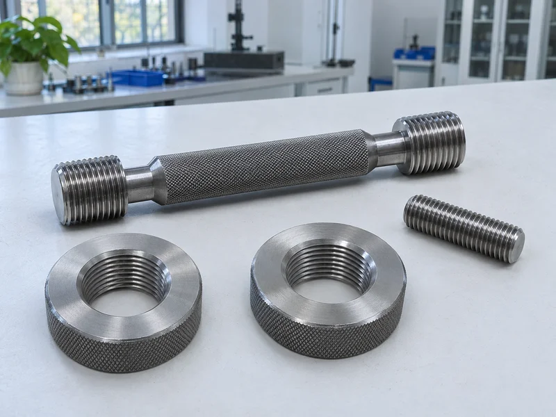
- GO end: represents the minimum material condition limit for assembly; must screw in fully by hand without force.
- NO-GO end: represents the maximum allowed size; must not enter more than a defined number of turns.
- Pass: GO enters fully, NO-GO does not.
- Fail: GO does not enter (too tight or damaged), or NO-GO enters (too loose).
For example, if the GO end stops halfway in a tapped hole, the thread may be undersize, damaged or have chips in it. Cleaning and re-gauging confirms the cause.
Key Takeaway: In other words, GO proves assembly; NO-GO proves the thread is not oversize.
Which Thread Classes Do Gauges Check?
Thread classes define tolerance positions and grades that gauges are made to.
| Standard | Internal thread | External thread | Typical use |
|---|---|---|---|
| ISO metric | 6H | 6g | General purpose |
| ISO metric (tighter) | 5H | 4h / 6h | Precision fits |
| Unified (inch) | 2B | 2A | General purpose |
| Unified (tighter) | 3B | 3A | Precision fits |
| Pipe threads | NPT, BSPT (taper) | NPT, BSPT | Fluid fittings |
For example, a precision instrument fitting may specify M8×1 5H, which needs a matching 5H plug gauge. Pipe threads use taper gauges with step tolerances. Our guide to quality issues in outsourced CNC turning instrumentation parts discusses fitting threads.
Key Takeaway: For this reason, the gauge class must match the drawing callout.
How Should Threads Be Gauged After Plating or Coating?
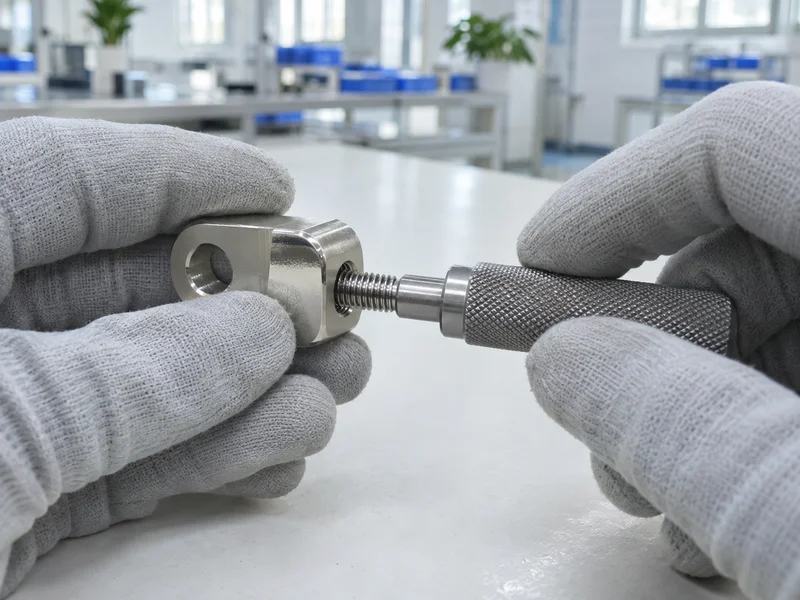
Threads should be gauged after plating or coating when the drawing requires the final thread to fit.
Considerations:
- Coatings add thickness to thread flanks, reducing internal thread size and increasing external size.
- Pre-plating allowance: tap or cut oversize to allow for coating.
- Masking threads during anodizing or powder coating.
- Gauge stage: state “thread gauge after plating” on the drawing.
For example, an internal M5 thread in a hard-anodized aluminum part may fail the GO gauge after coating unless it was tapped oversize or masked. Our guide to plating thickness explains coating allowances.
Key Takeaway: Overall, always specify whether threads are gauged before or after finishing.
How Should Thread Gauges Be Used and Cared For?
Thread gauges should be used gently and maintained carefully.
Use:
- Clean threads before gauging
- Turn by hand, never force
- Check GO full depth and NO-GO engagement
- Gauge representative samples or 100% for critical threads
Care:
- Clean and oil gauges after use
- Store in protective cases
- Calibrate at defined intervals
- Replace worn gauges
For example, a worn GO plug may pass undersize threads. Calibration records catch wear before it causes escapes. Our quality control and inspection process uses calibrated thread gauges.
Key Takeaway: Equally, an uncalibrated gauge gives false confidence.
What Causes Threads to Fail a Thread Gauge?
Threads fail a thread gauge for reasons that point to tooling, process or handling.
| Failure | Likely causes |
|---|---|
| GO does not enter | Undersize tap, worn tap, chips, burrs, coating buildup |
| NO-GO enters | Oversize tap, tap wobble, soft material tearing |
| Partial GO entry | Short thread depth, chips at bottom, damaged first threads |
| Inconsistent results | Tool wear trend, dirty gauge |
For example, threads that start passing NO-GO late in a batch often indicate tap wear changing the cut. Planned tool changes prevent it. Our guide to high volume CNC machined parts explains tool life control.
Key Takeaway: As a rule, track gauge failures by position in the batch to find tool wear.
How Should Thread Acceptance Be Specified on Drawings?
Thread acceptance should be specified on drawings with thread size, class, depth and gauging stage.
Specification items:
- Thread size and pitch, such as M6×1
- Class, such as 6H or 2B
- Full thread depth and drill depth
- Gauging stage: before or after coating
- Inspection level: sampling or 100%
For example, “M6×1-6H, 12 deep full thread, gauge after nickel plating, 100% GO/NO-GO” removes ambiguity. Thread gauge specifications are also published by ASTM International for some applications.
Key Takeaway: Finally, put the gauging stage on the drawing to prevent finishing disputes.
FAQ
- Q: What is a thread gauge?
- A precision tool that checks whether a thread is within its tolerance class.
- Q: How does a go/no-go thread plug gauge work?
- The GO end must enter fully; the NO-GO end must not enter beyond about two turns.
- Q: What is the difference between 6H and 6g?
- 6H is a metric internal thread class; 6g is the matching external class.
- Q: Should threads be gauged after plating?
- If the final assembly depends on the coated thread, yes, and the drawing should say so.
- Q: Why does a GO gauge fail?
- Undersize or worn taps, chips, burrs or coating buildup.
Conclusion
A thread gauge confirms that threads will assemble and are not oversize. Match gauge class to the drawing, gauge at the right stage, keep gauges calibrated and specify acceptance clearly. To review threads on your part, send your 3D model and 2D drawing to our engineers.