
Plating Thickness: Typical Values and Machining Allowance
Plating thickness is the thickness of a metal coating, such as zinc, nickel, electroless nickel, chrome, tin or silver, deposited on a machined part. It decides how long the coating protects against corrosion or wear, and it changes the part’s dimensions. Too thin, and the part rusts or wears early; too thick, and fits, threads and holes no longer pass inspection.
Many plating problems appear as dimensional failures after finishing. For example, a precision bore that measured perfectly after machining may fail its H7 gauge after 15 µm of nickel. In this guide, we explain plating thickness: typical values by coating, how thickness affects dimensions, how to plan machining allowances, why thickness varies across a part, how it is measured and how to specify it so parts are re-inspected correctly after plating. For plating choices, see our guide to copper and nickel plating.
Plating thickness is usually specified in micrometers: zinc about 5–25 µm, decorative nickel about 5–20 µm, electroless nickel about 5–25 µm (up to 50 µm or more for wear), hard chrome about 10–50 µm or more, and tin or silver a few micrometers. Plating adds its full thickness to each coated surface, so a diameter grows by twice the thickness. Electroplated thickness varies with geometry, thicker on edges and thinner in holes, while electroless nickel is uniform. Specify thickness range, measurement location, masking and whether dimensions apply before or after plating, and re-inspect critical dimensions after finishing.
In short: choose thickness for protection, allow for it in machining, and re-measure critical features after plating.
Key points:
- Thickness range: depends on coating and environment.
- Dimensional effect: doubles on diameters.
- Uniformity: electroplating varies; electroless nickel is even.
What Is Plating Thickness?
Plating thickness is the depth of the metal layer deposited on the base material.
Why it matters:
- Corrosion protection generally rises with thickness
- Wear resistance for hard coatings
- Dimensional change at fits, threads and holes
- Cost rises with thickness and plating time
For example, a zinc-plated steel bracket for indoor use may need 5–8 µm, while one for outdoor use may need 12–25 µm. Zinc plating specifications such as ISO 2081 are published by ISO.
Key Takeaway: Above all, plating thickness is both a performance and a dimensional requirement.
What Plating Thickness Is Typical for Each Coating?
Typical plating thickness depends on the coating and the service condition.
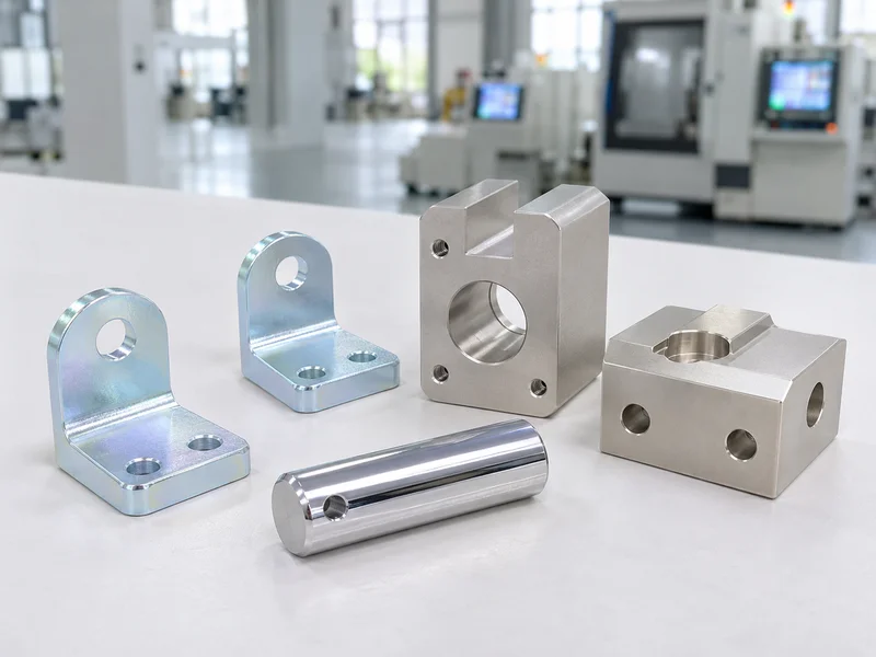
| Coating (typical) | Typical thickness | Main purpose |
|---|---|---|
| Zinc (with passivation) | 5–25 µm | Corrosion on steel |
| Decorative nickel | 5–20 µm | Appearance, corrosion |
| Electroless nickel | 5–25 µm (more for wear) | Uniform corrosion and wear |
| Hard chrome | 10–50 µm+ | Wear, hardness |
| Tin | 2–10 µm | Solderability, contacts |
| Silver | 2–10 µm | Electrical contacts |
| Gold (flash to functional) | 0.1–2 µm | Contacts |
For example, a hydraulic rod may use hard chrome, while a connector pin uses a thin gold layer over nickel. Our guide to metal surface finishing techniques compares finish families.
Key Takeaway: In other words, match plating thickness to environment and wear.
How Does Plating Change Dimensions?
Plating changes dimensions by adding material to every coated surface.
- External diameters: grow by 2 × thickness
- Internal diameters: shrink by 2 × thickness
- Flat thickness: grows by 2 × thickness if both faces plated
- Threads: pitch diameter changes, affecting gauge results
- Edges: may build up more with electroplating
For example, a Ø10.000 mm pin with 10 µm nickel becomes about Ø10.020 mm. If it was machined to the drawing’s upper limit, it may now be oversize. Our guide to tight tolerance machining explains tolerance planning.
Key Takeaway: For this reason, always double the thickness when calculating diameter changes.
How Do You Plan Machining Allowances for Plating?
You plan machining allowances for plating by machining the part to a pre-plating size that ends in tolerance after coating.
Steps:
- Confirm the coating thickness range.
- Calculate the change on each critical feature.
- Set pre-plating dimensions on the process sheet or drawing.
- Mask features that must not change.
- Re-inspect after plating.
For example, an H7 bore of Ø12 (+0/+0.018) with 8–12 µm EN should be machined to about Ø12.016–12.024 before plating so it ends near the middle of tolerance. Our guide to thread gauge explains gauging threads after coating.
Key Takeaway: Overall, plan the pre-plating size, not just the final size.
Why Does the Coating Vary Across a Part?
The coating varies across a part because electroplating current concentrates at edges and corners.
- Edges and corners: thicker (high current density)
- Holes and recesses: thinner (low current density)
- Electroless nickel: uniform, because no current is used
- Racking position affects thickness distribution
- Auxiliary anodes can improve uniformity
For example, a zinc-plated part may have 15 µm on outer edges but only 5 µm inside a deep hole. If internal corrosion protection matters, electroless nickel may be better. Our guide to CNC machining surface finish explains how base finish shows through coatings.
Key Takeaway: Equally, specify where thickness is measured, because it varies.
How Is Plating Thickness Measured?
Plating thickness is measured with non-destructive and destructive methods.
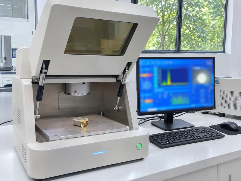
| Method | Principle | Typical use |
|---|---|---|
| Magnetic induction | Non-magnetic coating on steel | Zinc, chrome on steel |
| Eddy current | Non-conductive or different conductivity | Coatings on non-ferrous metals |
| X-ray fluorescence (XRF) | Element-specific | Thin and multilayer coatings |
| Coulometric | Dissolves coating locally | Precise lab checks |
| Cross-section | Microscope on cut sample | Reference, disputes |
For example, XRF can measure nickel and gold layers on a small connector without damaging it. Thickness measurement standards are published by ASTM International. Our quality control and inspection process checks coating thickness when specified.
Key Takeaway: As a rule, agree method and location for thickness checks.
How Should Plating Thickness Be Specified?
Plating thickness should be specified with range, standard, measurement location and dimensional status.
Specification items:
- Coating and standard, such as “EN per ASTM B733”
- Thickness range, such as 10–15 µm
- Measurement location (significant surfaces)
- Masking areas
- Dimensions before or after plating
- Post-plating inspection of critical features
For example, “Zinc plate ISO 2081 Fe/Zn 12, measured on significant surfaces; M6 threads gauged after plating; Ø8 H7 masked” is complete.
Key Takeaway: Finally, require re-inspection of critical dimensions after plating.
FAQ
- Q: What is plating thickness?
- The depth of a metal coating deposited on a part, usually in micrometers.
- Q: How thick is zinc plating?
- Typically about 5–25 µm depending on the environment.
- Q: How much does plating change a diameter?
- By twice the plating thickness.
- Q: Why is plating thinner in holes?
- Electroplating current concentrates on edges and is lower in recesses.
- Q: How is plating thickness measured?
- With magnetic, eddy current or XRF instruments, or by cross-section.
Conclusion
Plating thickness controls both protection and dimensions. Choose it by environment, allow for it in machining, specify where it is measured and re-inspect critical features after plating. To review a plated part, send your 3D model and 2D drawing to our engineers.