
GD&T Reference Dimension: When and How to Use It
A GD&T reference dimension is a dimension shown in parentheses on a drawing for information only. It is not toleranced, not inspected and not used for manufacturing decisions; it simply helps the reader understand the part, for example an overall length that results from other toleranced dimensions. Used correctly, reference dimensions make drawings easier to read. Used wrongly, they hide requirements or create disputes about what must be measured.
Reference dimensions cause confusion when they duplicate controlled dimensions or carry implied importance. For example, a supplier may reject parts because an overall length in parentheses is out by 0.3 mm, even though the drawing only controls the individual steps. In this guide, we explain the GD&T reference dimension: what it means, how it differs from basic dimensions, when to use it, common mistakes, how suppliers treat it and how to show it correctly. For the wider system, see our guide to GD&T geometric dimension & tolerance.
A GD&T reference dimension is shown in parentheses, for example (45), and is for information only: it has no tolerance, is not used for production or inspection acceptance, and usually repeats or derives from other dimensions. It differs from a basic dimension, shown in a rectangular box, which is an exact theoretical value used with a geometric tolerance. Reference dimensions are useful for overall sizes, derived values and clarity, but should never be the only definition of a requirement. ASME Y14.5 and ISO drawing standards define their use.
In short: parentheses mean information only; boxes mean exact values controlled by geometric tolerances.
Key points:
- Reference: parentheses, no tolerance, not inspected.
- Basic: box, exact value tied to a GD&T tolerance.
- Use: clarity, never the only requirement.
What Is a GD&T Reference Dimension?
A GD&T reference dimension is a dimension given for information, shown in parentheses.
Characteristics:
- No tolerance applies
- Not used for inspection acceptance
- Often redundant, derived from other dimensions
- Helps readers understand overall size or relationships
For example, a shaft drawing may control three step lengths with tolerances and show the overall length as (120) for reference. Drawing practice standards are published by ISO, including ISO 129-1.
Key Takeaway: Above all, a reference dimension informs; it does not control.
What Is the Difference Between a Reference and a Basic Dimension?
The difference between a reference and a basic dimension is how each is used.
| Feature | Reference dimension | Basic dimension |
|---|---|---|
| Shown as | In parentheses: (45) | In a box: [45] |
| Tolerance | None | From a GD&T feature control frame |
| Inspected | No | Yes, through the geometric tolerance |
| Purpose | Information | Defines exact theoretical location or profile |
For example, the location of a hole pattern is defined by basic dimensions with a position tolerance, while the part’s overall width may be a reference dimension. Our guide to GD&T position tolerance explains basic dimensions.
Key Takeaway: In other words, a box carries a requirement; parentheses carry information.
When Should You Use a GD&T Reference Dimension?
You should use a GD&T reference dimension when it adds clarity without creating a requirement.
Good uses:
- Overall lengths derived from toleranced steps
- Stock sizes for information
- Derived values such as a calculated angle
- Dimensions shown in another view, repeated for convenience
- Before-coating sizes given for information
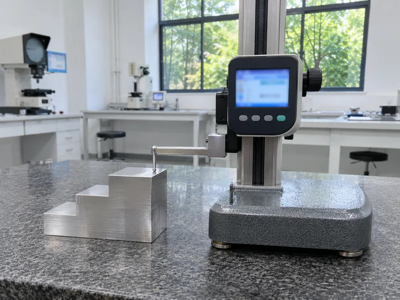
For example, showing the overall height (32) on a stepped bracket helps the reader, while the controlled steps define the part. Our guide to design for CNC machining covers drawing clarity.
Key Takeaway: For this reason, use reference dimensions to help readers, not to define features.
What Are Common Mistakes With Reference Dimensions?
Common mistakes with reference dimensions create confusion or missing requirements.
Mistakes:
- Critical features shown only as reference
- Reference values that conflict with toleranced dimensions
- Suppliers inspecting reference dimensions and rejecting parts
- Using parentheses for basic dimensions or vice versa
- Too many reference dimensions cluttering the drawing
For example, if a sealing groove depth appears only as (2.5), nobody is required to control it. Making it a toleranced dimension fixes the gap. Our guide to machining tolerance chart helps choose realistic tolerances.
Key Takeaway: Overall, never leave a functional feature as reference only.
How Do Suppliers Treat Reference Dimensions in Parentheses?
Suppliers treat reference dimensions in parentheses as information that does not need inspection.
Practice:
- Not ballooned for inspection, or marked “REF”
- Used for setup or sanity checks only
- Reported only if requested
- Questions raised if a reference conflicts with controlled dimensions
For example, a first article report usually skips reference dimensions, unless the customer asks for them. Our guide to the first article inspection report explains ballooning.
Key Takeaway: Equally, agree in advance if any reference dimension should be reported.
How Should a GD&T Reference Dimension Be Shown on Drawings?
A GD&T reference dimension should be shown clearly and consistently on drawings.
Rules:
- Use parentheses, or “REF” where that convention applies
- Do not add tolerances
- Avoid duplicating critical dimensions
- Check consistency with controlled dimensions
- Explain in a note if parentheses are used for another purpose
For example, a note “Dimensions in parentheses are for reference only” removes doubt for international suppliers. Our engineering and DFM review checks reference dimension use.
Key Takeaway: As a rule, one clear note avoids most reference dimension disputes.
How Do Reference Dimensions Affect Inspection Planning?
Reference dimensions affect inspection planning by being excluded from acceptance checks.

Planning:
- Inspection plans list only toleranced and GD&T features
- Reference values may be used as quick checks for gross errors
- Coating-related references help verify allowances
For example, if a part’s overall length differs from its reference value by 1 mm, an inspector may investigate even though it is not an acceptance criterion. Our quality control and inspection process follows the toleranced features on the drawing.
Key Takeaway: Finally, inspect requirements, and use references only as sanity checks.
FAQ
- Q: What is a reference dimension in GD&T?
- A dimension in parentheses for information only, without tolerance or inspection requirement.
- Q: What is the difference between reference and basic dimensions?
- Reference dimensions are information; basic dimensions are exact values controlled by geometric tolerances.
- Q: Are reference dimensions inspected?
- Normally not, unless the customer asks.
- Q: Can a reference dimension have a tolerance?
- No. If it needs a tolerance, it should be a normal dimension.
- Q: Why do drawings use reference dimensions?
- To show overall or derived sizes for clarity.
Conclusion
A GD&T reference dimension gives information without creating a requirement. Use it for clarity, keep functional features toleranced, distinguish it from basic dimensions and note the convention on the drawing. To review your drawing, send your 3D model and 2D drawing to our engineers.