
GD&T Geometric Dimension & Tolerance: Key Symbols Explained
GD&T geometric dimension & tolerance is the symbolic language engineers use to define how much the form, orientation, location and runout of features may vary. Instead of relying only on ± dimensions, GD&T uses datums and tolerance zones that match how a part functions in its assembly. For machined parts, it tells the machinist which features matter most and tells the inspector exactly how to measure them.
GD&T is powerful but often misunderstood on the shop floor. For example, a drawing may call flatness where parallelism was intended, or concentricity where runout would be easier to measure and just as functional. In this guide, we explain GD&T geometric dimension & tolerance for machined parts: the main tolerance categories, datums, flatness vs parallelism, runout vs concentricity, hole pattern datum shift, and how GD&T connects to first article approval. For specific controls, see our guides to GD&T position tolerance and GD&T profile tolerance.
GD&T geometric dimension & tolerance, defined by ASME Y14.5 and ISO 1101/GPS standards, controls features with symbols in feature control frames. Its main categories are form (flatness, straightness, circularity, cylindricity), orientation (parallelism, perpendicularity, angularity), location (position, and in older practice concentricity and symmetry), profile (line and surface) and runout (circular and total). Datums establish the reference frame. Modifiers such as MMC allow bonus tolerance and datum shift. Good GD&T reflects function, uses measurable controls and supports clear first article inspection.
In short: GD&T describes function with datums and zones; choose controls that are functional and measurable.
Key points:
- Categories: form, orientation, location, profile, runout.
- Datums: the reference frame from function.
- Measurability: prefer controls inspectors can verify.
What Is GD&T Geometric Dimension & Tolerance?
GD&T geometric dimension & tolerance is a standardized system for defining allowable variation in part geometry.
Core elements:
- Feature control frame: symbol, tolerance value, modifiers, datums
- Datums: reference features (A, B, C)
- Basic dimensions: exact theoretical values, boxed on the drawing
- Tolerance zones: the space where the feature must lie
For example, a hole with “position Ø0.1 Ⓜ A B C” must have its axis within a 0.1 mm cylinder located by basic dimensions from datums A, B and C. Standards are published by ISO, such as ISO 1101.
Key Takeaway: Above all, GD&T defines zones relative to datums, not just sizes.
What Are the Main Categories of GD&T Geometric Dimension & Tolerance?
The main categories of GD&T geometric dimension & tolerance group controls by what they limit.
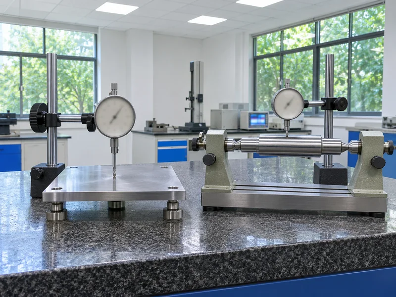
| Category | Controls | Datums needed |
|---|---|---|
| Form | Flatness, straightness, circularity, cylindricity | No |
| Orientation | Parallelism, perpendicularity, angularity | Yes |
| Location | Position (concentricity, symmetry in older practice) | Yes |
| Profile | Profile of a line, profile of a surface | Optional |
| Runout | Circular runout, total runout | Yes |
For example, a mounting face may need flatness only, while a bearing bore needs perpendicularity to the mounting face and position to locating holes. Our guide to all around symbol GD&T covers profile scope.
Key Takeaway: In other words, form controls stand alone; orientation, location and runout need datums.
What Is the Difference Between Flatness and Parallelism in Machining?
The difference between flatness and parallelism in machining is the reference: flatness controls a surface by itself, while parallelism controls it relative to a datum.
- Flatness: all points of the surface lie between two parallel planes; no datum.
- Parallelism: the surface lies between two planes parallel to a datum.
- Parallelism includes flatness for that surface.
- Neither controls size; size is controlled separately.
For example, a sealing face needs flatness; a spacer whose two faces must stay parallel for clamping needs parallelism to the opposite face. Our guide to GD&T surface finish explains how finish affects flatness measurement.
Key Takeaway: For this reason, use flatness for sealing and parallelism for stacking or clamping.
What Is the Difference Between Runout and Concentricity on Turned Parts?
The difference between runout and concentricity on turned parts is what they measure and how easily.
- Circular runout: variation of a surface during one rotation about a datum axis; easy with an indicator.
- Total runout: variation over the whole surface; controls form and orientation too.
- Concentricity: median points of a feature relative to a datum axis; hard to measure, removed from ASME Y14.5-2018.
- Position (RFS) often replaces concentricity for coaxial features.
For example, a shaft seat specified with circular runout 0.01 to A-B can be checked quickly between centers, while concentricity would need CMM analysis. Our guide to high precision CNC turning explains runout control.
Key Takeaway: Overall, prefer runout or position over concentricity for turned parts.
What Is Datum Shift in Machined Hole Patterns?
Datum shift in machined hole patterns is the extra freedom a pattern gains when a datum feature of size is referenced at MMC and departs from MMC.
How it works:
- Datum feature at MMC (Ⓜ): the datum hole or pin can shift within its own clearance.
- Result: the hole pattern may move relative to the datum without failing.
- Function: matches assembly behavior with clearance fits.
- Inspection: functional gauges or CMM with datum shift calculation.
For example, a bolt pattern referenced to a center bore at MMC can shift slightly if the bore is made larger, just as the mating part would. Our guide to CMM measurement explains datum setup.
Key Takeaway: Equally, datum shift gives tolerance that the assembly can actually accept.
How Should GD&T Geometric Dimension & Tolerance Be Applied to Machined Parts?
GD&T geometric dimension & tolerance should be applied to machined parts so it reflects function and stays measurable.
Good practice:
- Datums from assembly interfaces
- Position for hole patterns instead of ± coordinates
- Profile for complex outlines
- Runout for rotating features
- MMC where clearance fits allow bonus tolerance
- General tolerance note for non-critical features
For example, replacing ±0.05 mm coordinates on a four-hole pattern with position Ø0.1 Ⓜ gives a larger, functional tolerance zone. Our guide to machining tolerance chart explains process capabilities.
Key Takeaway: As a rule, GD&T should make tolerances more functional, not just more complex.
How Does GD&T Connect to CNC Machining First Article Approval?
GD&T connects to CNC machining first article approval because each control becomes a measured characteristic in the first article report.
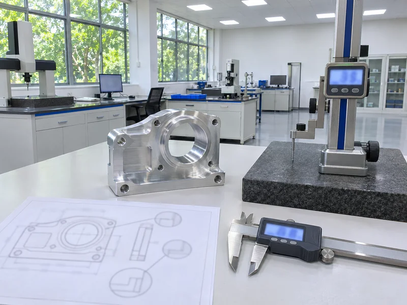
First article practice:
- Ballooned drawing with every GD&T callout numbered
- Measurement method stated for each control
- Datum setup matching the drawing
- Results with actual values and pass/fail
- Approval before production release
For example, a first article report that lists “position of 4× Ø6.6: 0.06 / 0.1 Ⓜ, pass” shows the pattern meets the requirement. Our guide to the first article inspection report explains the format, and our quality control and inspection process supplies reports on request.
Key Takeaway: Finally, every GD&T control should have a planned measurement before the first part is made.
FAQ
- Q: What is GD&T?
- A symbolic system for defining allowable variation in form, orientation, location, profile and runout.
- Q: What is the difference between flatness and parallelism?
- Flatness needs no datum; parallelism is relative to a datum and includes flatness.
- Q: Why is runout preferred over concentricity?
- Runout is easier to measure and often controls the same function.
- Q: What is datum shift?
- Extra tolerance when a datum feature of size is referenced at MMC and departs from MMC.
- Q: How is GD&T verified on first articles?
- Each callout is measured and reported against a ballooned drawing.
Conclusion
GD&T geometric dimension & tolerance turns function into measurable requirements. Use datums from assembly interfaces, choose flatness or parallelism and runout or position wisely, apply MMC where it helps and plan first article measurements. To review GD&T on your drawing, send your 3D model and 2D drawing to our engineers.