
All Around Symbol GD&T: Meaning and Correct Callouts
The all around symbol GD&T drawings use is a small circle placed at the bend of a leader line, telling the reader that a profile tolerance applies all the way around the outline shown in that view. It saves drawing clutter on machined and molded parts with continuous outlines, such as flanges, cover plates, gaskets and housing perimeters. Used carelessly, though, it can apply a tolerance to surfaces the designer never meant to control, or leave gaps nobody notices.
The symbol is simple, but its scope causes confusion. For example, an all around profile on the top view of a stepped housing controls only the outline seen in that view, not every face of the part. In this guide, we explain the all around symbol GD&T standards define: what it means, how it works with profile tolerances, how it differs from all over and between symbols, how to apply it correctly, and how machinists and inspectors handle it. For profile basics, see our guide to GD&T profile tolerance.
The all around symbol GD&T uses is a small circle at the elbow of the leader line from a feature control frame. It means the profile tolerance (profile of a line or profile of a surface) applies to all surfaces of the outline shown in that view, continuing around the entire contour. It applies only to the elements in that view’s outline, not to all surfaces of the part. The related “all over” symbol (two concentric circles in ASME Y14.5-2018) applies a profile tolerance to all surfaces of the part, and the “between” symbol limits a tolerance to a section between two labeled points.
In short: the all around circle extends a profile tolerance around the outline in that view, not over the whole part.
Key points:
- Symbol: small circle at the leader bend.
- Scope: the outline shown in that view.
- Alternatives: all over and between symbols for other scopes.
What Does the All Around Symbol GD&T Uses Mean?
The all around symbol GD&T uses means the attached profile tolerance applies all around the outline shown in the view.
Key points:
- Used with profile tolerances: profile of a line or profile of a surface
- Applies to the view’s outline: all surfaces that form the contour
- Saves repetition: one callout instead of many
- Datums can still be referenced in the frame
For example, a cover plate outline with an all around profile of a surface 0.2 relative to A, B and C controls every edge face around the perimeter. GD&T symbols are defined in ASME Y14.5 and ISO 1101, published by ISO.
Key Takeaway: Above all, the circle extends the tolerance around one outline.
How Does the All Around Symbol GD&T Callout Work With Profile Tolerances?
The all around symbol GD&T callout works with profile tolerances by applying the same tolerance zone to each surface of the contour.
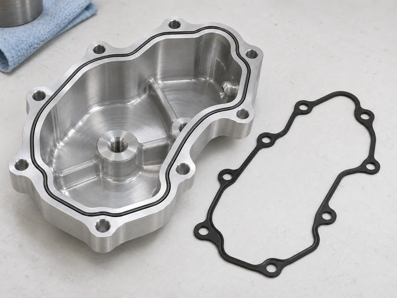
How it works:
- Profile of a surface: controls the full surfaces around the outline
- Profile of a line: controls cross-sections around the outline
- Zone: equal bilateral by default; unequal with U or UZ modifiers
- Datums: add location and orientation control
For example, an all around profile of a surface 0.1 A B C on a pocket wall controls its shape and position relative to the part datums. Our guide to GD&T position tolerance explains datum frames.
Key Takeaway: In other words, all around simply repeats the profile zone around the contour.
How Does All Around Differ From All Over and Between Symbols?
All around differs from all over and between symbols by the scope of surfaces they control.
| Symbol | Appearance | Scope |
|---|---|---|
| All around | Small circle at leader bend | Outline in that view |
| All over | Two concentric circles (ASME 2018) | All surfaces of the part |
| Between | Double-headed arrow between labels | Section between two points |
For example, a designer who wants every surface of a freeform molded part controlled may use all over, while a flange outline uses all around. Our guide to GD&T geometric dimension & tolerance explains the wider system.
Key Takeaway: For this reason, choose the symbol whose scope matches the surfaces you intend to control.
How Should the All Around Symbol GD&T Callout Be Applied?
The all around symbol GD&T callout should be applied on drawings to a view where the intended outline is clear.
Good practice:
- Choose the view that shows the full contour
- Place the circle at the bend of the leader line
- Reference datums if location matters
- Exclude surfaces with separate callouts if needed
- Avoid ambiguity on parts with steps or hidden outlines
For example, on a stepped housing, applying all around to the top-view outline controls only the outer perimeter; inner pocket walls need their own callouts. Our engineering and DFM review checks such callouts.
Key Takeaway: Overall, check which surfaces the chosen view actually shows.
What Are Common Mistakes With the All Around Symbol?
Common mistakes with the all around symbol include unclear scope and unintended control.
Mistakes:
- Assuming it covers the whole part instead of the view outline
- Applying it in a view with ambiguous edges
- Forgetting datums when location matters
- Over-tight values on cast or molded outlines
- Conflicts with other dimensions on the same surfaces
For example, a tight all around profile on a molded housing perimeter may be costly to hold if only two edges actually mate. Our guide to injection molding tolerances explains realistic molded values.
Key Takeaway: Equally, tolerance only the outline surfaces that matter.
How Do Machinists and Inspectors Handle All Around Callouts?
Machinists and inspectors handle all around callouts by treating the outline as one controlled profile.

Machining:
- Contour finishing passes around the full outline
- Consistent datums for setups
Inspection:
- CMM scanning around the outline
- Comparison to the CAD model within the zone
- Reporting worst deviation and location
For example, a CMM scan of a cover outline with an all around profile shows any point outside the 0.2 mm zone. Our guide to CMM measurement explains scanning. Our quality control and inspection process reports profile results on request.
Key Takeaway: As a rule, ask for a deviation map for all around profiles.
When Should You Use the All Around Symbol?
You should use the all around symbol when a continuous outline needs one consistent profile control.
Good uses:
- Flange and cover plate outlines
- Gasket and seal contours
- Pocket perimeters that mate with inserts
- Molded part outlines that fit into housings
Avoid it when:
- Only some edges matter
- Different tolerances are needed on different sides
For example, a gasket contour that must seal all around is a good case, while a bracket with one critical edge needs only that edge controlled.
Key Takeaway: Finally, use all around when the whole outline truly matters.
FAQ
- Q: What is the all around symbol in GD&T?
- A small circle at the leader bend meaning the profile tolerance applies around the outline in that view.
- Q: Does all around apply to the whole part?
- No. It applies to the outline shown in that view; all over applies to the whole part.
- Q: Which tolerances use the all around symbol?
- Profile of a line and profile of a surface.
- Q: What is the between symbol?
- A symbol limiting a tolerance to the section between two labeled points.
- Q: How is an all around profile inspected?
- Usually by CMM scanning against the CAD model.
Conclusion
The all around symbol GD&T uses extends a profile tolerance around one outline, saving drawing clutter when the whole contour matters. Choose the view carefully, reference datums and tolerance only what functions. To review GD&T on your drawing, send your 3D model and 2D drawing to our engineers.