
Machining Tolerance Chart: ISO Grades and General Tolerances
A machining tolerance chart shows what tolerances are typical or achievable for different processes, feature sizes and tolerance grades. Designers use it to choose realistic tolerances, and buyers use it to judge whether a drawing will be expensive to make. Without one, it is easy to ask for ±0.005 mm on a milled pocket that only needs ±0.1 mm, or to expect turning to hold what only grinding can.
Charts are guides, not guarantees. For example, an IT7 bore is routine on a 20 mm reamed hole in aluminum, but harder on a thin-walled stainless sleeve that distorts when clamped. In this guide, we provide a practical machining tolerance chart: ISO tolerance grades, typical tolerances by process, general tolerance classes, how feature size and material change what is realistic, and how to use the chart on drawings. For targeted tolerancing, see our guide to tight tolerance machining.
A machining tolerance chart links processes and feature sizes to typical achievable tolerances, usually expressed as ISO 286 IT grades. Typical ranges: rough milling and turning IT11–IT13; finish milling IT8–IT10; finish turning IT7–IT9; reaming and boring IT6–IT8; grinding IT5–IT7; honing and lapping IT4–IT6; wire EDM roughly IT6–IT8 depending on passes. The tolerance width in millimeters grows with feature size for the same grade. General tolerances such as ISO 2768 (f, m, c, v) cover features without individual tolerances. Material, wall thickness, temperature and setups affect what is achievable in practice.
In short: use the chart to match tolerance to process, then adjust for size, material and part stiffness.
Key points:
- IT grades: standard tolerance widths by size.
- Process capability: each process has a typical IT range.
- Practical limits: material and part stiffness matter.
What Is a Machining Tolerance Chart?
A machining tolerance chart is a reference that links manufacturing processes to the tolerances they typically achieve.
It usually covers:
- Processes: milling, turning, drilling, reaming, boring, grinding, EDM
- Tolerance grades: ISO 286 IT grades
- Feature size ranges
- Surface finish often listed alongside
For example, a chart helps decide that a Ø10 H7 bore should be reamed or bored, not just drilled. ISO 286 tolerance grades are published by ISO.
Key Takeaway: Above all, a chart connects what the drawing asks for with how it will be made.
What Does a Typical Machining Tolerance Chart Show?
A typical machining tolerance chart by process looks like this (guidance only):
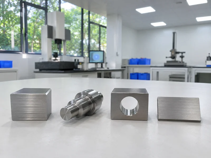
| Process | Typical IT grade | Typical tolerance on a 25 mm feature |
|---|---|---|
| Rough milling / turning | IT11–IT13 | about ±0.07–0.17 mm |
| Finish milling | IT8–IT10 | about ±0.017–0.04 mm |
| Finish turning | IT7–IT9 | about ±0.01–0.026 mm |
| Drilling | IT10–IT12 | about ±0.04–0.1 mm |
| Reaming / boring | IT6–IT8 | about ±0.007–0.017 mm |
| Grinding | IT5–IT7 | about ±0.005–0.01 mm |
| Honing / lapping | IT4–IT6 | about ±0.003–0.007 mm |
| Wire EDM | IT6–IT8 | about ±0.007–0.017 mm |
Values are approximate; machine capability is not finished-part tolerance. Our Dongguan factory uses wire EDM and Okamoto grinders for the tightest features.
Key Takeaway: In other words, the process sets the realistic tolerance band.
How Do ISO Tolerance Grades Work?
ISO tolerance grades work by defining a tolerance width that grows with nominal size.
| IT grade | 10–18 mm | 18–30 mm | 30–50 mm |
|---|---|---|---|
| IT5 | 8 µm | 9 µm | 11 µm |
| IT6 | 11 µm | 13 µm | 16 µm |
| IT7 | 18 µm | 21 µm | 25 µm |
| IT8 | 27 µm | 33 µm | 39 µm |
| IT9 | 43 µm | 52 µm | 62 µm |
| IT11 | 110 µm | 130 µm | 160 µm |
For example, H7 on a 25 mm bore means a total tolerance of 21 µm above nominal. Our guide to tolerance for slip fit explains fit letters.
Key Takeaway: For this reason, the same IT grade is wider on larger features.
How Do General Tolerances Fit Into a Machining Tolerance Chart?
General tolerances fit into a machining tolerance chart as the default for features without individual tolerances.
ISO 2768-1 linear tolerances (examples):
| Size range | f (fine) | m (medium) | c (coarse) |
|---|---|---|---|
| 6–30 mm | ±0.1 | ±0.2 | ±0.5 |
| 30–120 mm | ±0.15 | ±0.3 | ±0.8 |
| 120–400 mm | ±0.2 | ±0.5 | ±1.2 |
For example, a bracket drawn to ISO 2768-m holds ±0.2 mm on a 25 mm length without extra notes. The standard is available from ISO 2768.
Key Takeaway: Overall, use a general class for most features and individual tolerances for functional ones.
How Do Size, Material and Stiffness Change Achievable Tolerances?
Size, material and stiffness change achievable tolerances because they affect distortion, temperature and measurement.
- Larger features: wider tolerance in mm for the same grade
- Long or thin parts: distortion and springback
- Plastics: thermal expansion and moisture
- Hard materials: may need grinding
- Temperature: aluminum grows about 0.023 mm per meter per °C
For example, IT7 on a rigid steel bushing is routine, while IT7 on a thin nylon sleeve is unrealistic. Our guide to machining polycarbonate compares plastic stability.
Key Takeaway: Equally, adjust chart values for real part stiffness and material.
How Should You Use a Machining Tolerance Chart on Drawings?
You should use a machining tolerance chart on drawings to choose the loosest tolerance that still works.
Steps:
- Identify functional features.
- Choose fits or tolerances from function.
- Check the chart for the process needed.
- Relax tolerances where a cheaper process is enough.
- Use a general tolerance for the rest.
For example, if a hole only clears a bolt, ISO 2768-m is enough; if it locates a dowel, H7 by reaming is needed. Our guide to design for CNC machining covers other design rules.
Key Takeaway: As a rule, every tolerance tighter than the general class should have a functional reason.
How Are Chart Tolerances Verified?
Chart tolerances are verified with measuring equipment much more accurate than the tolerance.
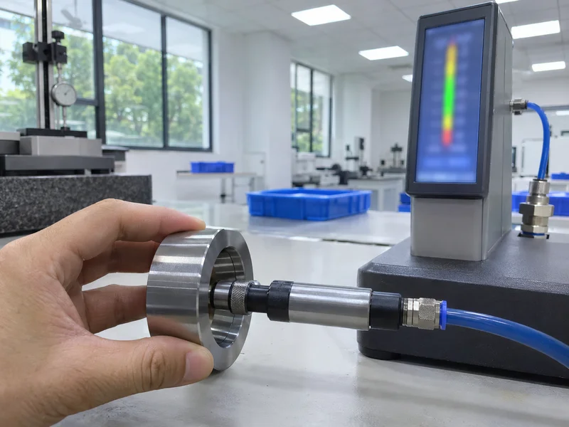
Verification:
- Calipers for general tolerances
- Micrometers and bore gauges for IT7–IT9
- Air gauges and CMM for IT5–IT7
- Temperature control for tight work
- First article inspection on new parts
For example, measuring an IT6 bore needs a bore gauge or air gauge, not a caliper. Our quality control and inspection process supplies dimensional reports on request.
Key Takeaway: Finally, the gauge must resolve about one tenth of the tolerance.
FAQ
- Q: What is a machining tolerance chart?
- A reference linking processes and feature sizes to typical achievable tolerances.
- Q: What tolerance can CNC milling hold?
- Finish milling typically holds about IT8–IT10, tighter with care.
- Q: What does IT7 mean?
- An ISO tolerance grade; for 18–30 mm it is a 21 µm total tolerance.
- Q: What is ISO 2768-m?
- A medium general tolerance class, for example ±0.2 mm for 6–30 mm lengths.
- Q: Which process gives the tightest tolerances?
- Grinding, honing and lapping.
Conclusion
A machining tolerance chart helps match tolerances to processes, but real results depend on size, material and stiffness. Use general tolerances for most features, targeted tolerances for functional ones, and verify with suitable gauges. To review tolerances on a drawing, send your 3D model and 2D drawing to our engineers.