
Design for CNC Machining: Corners, Walls, Holes, Setups
Design for CNC machining means shaping a part so it can be machined accurately, quickly and with standard tools, without losing its function. Small design choices, such as an internal radius, a pocket depth, a hole size or a tolerance, decide whether a part needs one setup with standard cutters or several setups with special tools. For small and medium precision parts, good design is often the biggest single factor in cost and lead time.
Most designers learn CNC rules the hard way. For example, a housing with sharp internal corners in deep pockets looks fine in CAD but cannot be cut without EDM, while a 3 mm corner radius lets a standard end mill finish it in minutes. In this guide, we explain design for CNC machining: internal corners and pockets, walls and thin features, holes and threads, setups and access, tolerances and finishes, material choice and how a DFM review helps. For cost effects, see our guide to custom CNC milling cost.
Design for CNC machining follows a few core rules: give internal corners a radius slightly larger than a standard tool radius; keep pocket depth within about 3–4 times the tool diameter; keep metal walls above about 0.8–1 mm and plastic walls above about 1.5 mm where possible; use standard drill and thread sizes with thread depth about 1.5–2 × diameter; group features so the part can be machined in few setups; apply tight tolerances and fine finishes only to functional features; and choose machinable materials. A DFM review before release catches problems early.
In short: design for standard tools, few setups and targeted tolerances.
Key points:
- Radii and depth: match standard tools.
- Setups: group features by direction.
- Tolerances: tight only where needed.
Why Does Design for CNC Machining Matter?
Design for CNC machining matters because geometry decides tools, setups and cycle time.
Effects of design:
- Tool size: small radii and narrow slots force small, slow tools
- Setups: features on many faces add clamping and alignment
- Accuracy: fewer setups keep features related
- Lead time: special tools and processes add days
- Cost: machine time and handling dominate price
For example, changing a bracket so all holes face one direction can remove a second setup. Our engineering and DFM review checks such opportunities.
Key Takeaway: Above all, most machining cost is decided at the design stage.
How Should Internal Corners and Pockets Be Designed for CNC Machining?
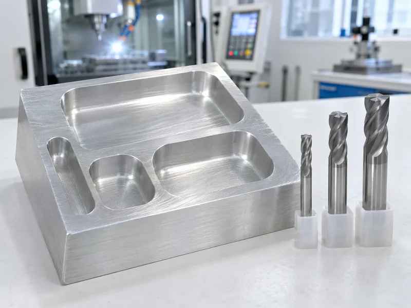
Internal corners and pockets should be designed for CNC machining to suit round cutters.
Rules:
- Internal radius: slightly larger than the tool radius, for example 3.2 mm with a 6 mm end mill
- Pocket depth: within about 3–4 × tool diameter; deeper needs long tools and slower cutting
- Floor radius: match standard bull-nose or ball cutters if specified
- Square corners: use relief cuts (dog-bones) or EDM if truly needed
For example, a 20 mm deep pocket with 1 mm corner radii forces a 2 mm tool that cuts very slowly; 4 mm radii allow an 8 mm tool. Our guide to the machining milling process explains tools and strategies.
Key Takeaway: In other words, the corner radius chooses the tool, and the tool sets the cycle time.
How Should Walls and Thin Features Be Designed?
Walls and thin features should be designed thick enough to resist vibration and distortion.
Guidelines (typical):
- Metal walls: above about 0.8–1 mm
- Plastic walls: above about 1.5 mm
- Tall thin walls: keep height-to-thickness ratio moderate
- Thin ribs: avoid unsupported thin ribs
- Thin floors: support or thicken where possible
For example, a 0.5 mm aluminum wall 20 mm tall may chatter and bend, while 1.2 mm machines cleanly. Our guide to CNC machining fixtures explains support for thin parts.
Key Takeaway: For this reason, thicken walls before tightening tolerances on them.
How Should Holes and Threads Be Designed?
Holes and threads should be designed with standard sizes and realistic depths.
Holes:
- Standard drill sizes
- Depth within about 4–6 × diameter for normal drilling
- Flat or drill-point bottoms stated clearly
- Reamed holes for precise fits
Threads:
- Standard thread sizes (metric or UNC/UNF)
- Thread depth about 1.5–2 × diameter
- Drill depth deeper than thread depth for blind holes
- Avoid very small threads in hard materials
For example, specifying M6 × 12 deep thread with a 15 mm drill depth avoids broken taps. Our guide to threaded holes explains callouts.
Key Takeaway: Overall, standard holes and threads use standard tools and cost less.
How Do Setups and Access Affect Design for CNC Machining?
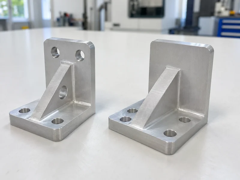
Setups and access affect design for CNC machining because every new direction can mean another clamping.
Design tips:
- Group features on one or two faces
- Avoid features hidden behind others
- Provide flat clamping surfaces
- Use 3+2 or 5-axis access only when necessary
- Machine datums first so later setups can locate on them
For example, a sensor housing redesigned so its connector port faces the same side as its mounting holes may drop from three setups to two. Our guide to multi axis CNC machining explains when extra axes help.
Key Takeaway: Equally, count setups while designing, not after quoting.
How Should Tolerances and Finishes Be Applied?
Tolerances and finishes should be applied only where function needs them.
Practice:
- General tolerance such as ISO 2768-m for most features
- Tight tolerances on fits, locations and seals
- GD&T for position, flatness and runout where needed
- Surface finish symbols on functional surfaces only
- Coating allowances for anodizing or plating
For example, a bracket with ISO 2768-m generally and ±0.01 mm only on two dowel holes is cheaper and clearer than one with ±0.01 mm everywhere. Our guide to tight tolerance machining explains targeted tolerances.
Key Takeaway: As a rule, every tight tolerance should have a reason.
How Does Material Choice Affect Design for CNC Machining?
Material choice affects design for CNC machining through machinability, stability and finishing.
- Aluminum (6061, 7075): fast, stable, anodizes well
- Stainless steel: slower; consider 303 where corrosion needs allow
- Brass: very fast for turned parts
- Titanium: slow; design for stiffness and access
- Plastics: POM is most stable; nylon absorbs moisture
For example, a part in 6061-T6 instead of 304 stainless may machine several times faster if corrosion requirements allow. Our guide to aluminium alloy 6061 properties explains why 6061 is the default.
Key Takeaway: Finally, choose the most machinable material that meets the function.
FAQ
- Q: What is design for CNC machining?
- Designing parts so they can be machined accurately and economically with standard tools and few setups.
- Q: What internal radius should I use?
- Slightly larger than a standard tool radius, for example 3.2 mm for a 6 mm end mill.
- Q: How deep can a pocket be?
- Ideally within about 3–4 times the tool diameter.
- Q: What is the minimum wall thickness for CNC parts?
- Typically about 0.8–1 mm for metals and 1.5 mm for plastics.
- Q: How can I reduce CNC machining cost through design?
- Use standard radii and holes, fewer setups and tight tolerances only where needed.
Conclusion
Design for CNC machining comes down to standard tools, few setups, sensible walls and targeted tolerances. Apply these rules early and use a DFM review before release. To review your design, send your 3D model and 2D drawing to our engineers.