
GD&T Surface Finish: Symbols, Parameters and Values
GD&T surface finish requirements tell the machinist and the inspector how smooth or textured a surface must be, alongside the geometric tolerances that control its size, form and position. Surface texture symbols on drawings specify parameters such as Ra or Rz, the lay direction, the manufacturing method and sometimes sampling details. They matter most on sealing faces, bearing and sliding surfaces, cosmetic faces and surfaces that will be plated or bonded.
Surface finish is often specified badly: either missing on critical faces or applied as a blanket tight value to every surface. For example, a drawing with “Ra 0.8 all over” can double machining time on a bracket where only two bores need that finish. In this guide, we explain GD&T surface finish: how surface texture symbols work, which parameters to use, how finish relates to tolerances, realistic values by process, how to apply it on drawings and how it is measured. For roughness parameters, see our guide to surface roughness Ra vs Rz.
GD&T surface finish is specified with the surface texture symbol defined in ISO 1302 / ISO 21920 or ASME Y14.36. The symbol’s basic check mark can indicate whether material removal is required, prohibited or optional, and carries the roughness parameter and value (for example Ra 1.6 µm or Rz 6.3 µm), plus optional lay direction, process and sampling information. Surface finish is separate from form tolerances such as flatness, but tight tolerances usually need finer finishes. Apply fine finishes only to functional surfaces, use a general note for the rest, and confirm measurement method and filter settings.
In short: use surface texture symbols on functional faces, a general note elsewhere, and match finish to tolerance.
Key points:
- Symbol: check mark with parameter, value and optional lay.
- Separate but linked: finish is not flatness, but they interact.
- Targeted: fine finish only where function needs it.
What Is GD&T Surface Finish?
GD&T surface finish is the specification of surface texture on an engineering drawing, used together with geometric tolerances.
It controls:
- Roughness: fine, closely spaced irregularities (Ra, Rz)
- Waviness: longer-wavelength variations
- Lay: the direction of the dominant pattern
- Flaws: defects such as scratches, often by separate notes
For example, an O-ring groove may carry “Ra 0.8 µm, circumferential lay”, while a mounting face carries “Ra 3.2 µm”. Surface texture standards are published by ISO, including ISO 1302 and ISO 21920.
Key Takeaway: Above all, surface finish describes texture, not shape or position.
How Does the GD&T Surface Finish Symbol Work?
The GD&T surface finish symbol works by combining a basic check mark with parameters and notes.
| Symbol element | Meaning |
|---|---|
| Basic check mark | Surface texture requirement |
| Check mark with bar | Material removal required (machined) |
| Check mark with circle | Material removal not permitted |
| Value with parameter | For example Ra 1.6 or Rz 6.3 |
| Lay symbol | =, ⊥, X, M, C, R directions |
| Process note | For example “ground” or “lapped” |
For example, a check mark with a bar and “Ra 0.4” on a shaft journal means the surface must be machined to Ra 0.4 µm or better. Our guide to GD&T profile tolerance explains related controls.
Key Takeaway: In other words, the symbol tells both the value and how it may be produced.
Which Parameters Should GD&T Surface Finish Use?
GD&T surface finish should use parameters that match the function.
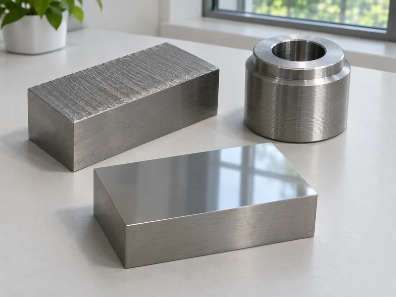
- Ra: average roughness; most common, simple to compare
- Rz: average peak-to-valley height; better for sealing and peaks
- Rmax / Rt: largest peak-to-valley; catches isolated scratches
- Rpk, Rvk, Mr: bearing-ratio parameters for sliding and lubrication surfaces
For example, a sealing face may need both Ra 0.8 and Rz 4 to avoid deep scratches that Ra alone could hide. Our guide to quality issues in outsourced CNC turning instrumentation parts shows why sealing surfaces need extra criteria.
Key Takeaway: For this reason, add Rz or a scratch note on sealing faces.
How Does Surface Finish Relate to GD&T Tolerances?
Surface finish relates to GD&T tolerances because rough surfaces make tight form and size tolerances hard to measure and hold.
Guidance:
- Tight size tolerance (for example IT6–IT7): finer finish, often Ra 0.4–1.6 µm
- Flatness of a few microns: needs ground or lapped surfaces
- Position of holes: usually independent of finish
- Fits: rough bores change effective fit
For example, a ±0.005 mm bore cannot be held reliably with Ra 3.2 µm, because peaks alone are a large part of the tolerance. Our guide to tight tolerance machining explains process choices.
Key Takeaway: Overall, match finish to tolerance; rough finish undermines tight tolerances.
What GD&T Surface Finish Values Are Realistic by Process?
Realistic GD&T surface finish values depend on the machining process.
| Process (typical) | Typical Ra range |
|---|---|
| Rough milling | 3.2–6.3 µm |
| Finish milling | 0.8–3.2 µm |
| Finish turning | 0.4–1.6 µm |
| Reaming | 0.8–1.6 µm |
| Grinding | 0.1–0.8 µm |
| Honing and lapping | 0.05–0.4 µm |
| Wire EDM (finish passes) | 0.4–1.6 µm |
For example, a milled pocket floor at Ra 1.6 µm is routine, while Ra 0.2 µm requires grinding or polishing. Our CNC machining services include milling, turning, grinding and EDM.
Key Takeaway: Equally, each step finer in finish may add a process step.
How Should GD&T Surface Finish Be Applied on Drawings?
GD&T surface finish should be applied with a general note plus specific symbols on functional surfaces.
Practice:
- General note: for example “unless otherwise specified, Ra 3.2 µm”
- Specific symbols: on sealing, bearing, sliding and cosmetic faces
- Lay direction where it matters
- Finish before or after coating clearly stated
- Avoid “all over” fine finishes
For example, “UOS Ra 3.2; Ra 0.8 on Ø20 H7 bore; Ra 0.4 circumferential on seal diameter” gives clear targets. Our guide to CNC machining cost for custom parts shows how finish affects cost.
Key Takeaway: As a rule, one general note plus targeted symbols keeps drawings clear and cost-effective.
How Is Surface Finish Measured?
Surface finish is measured with profilometers or optical instruments, using defined filters and lengths.
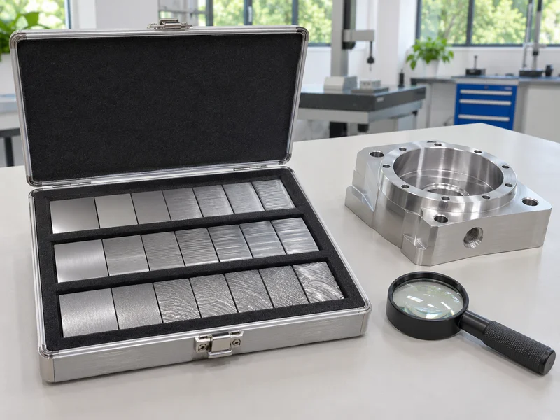
Measurement points:
- Contact profilometer with stylus traces
- Optical instruments for delicate or complex surfaces
- Cut-off and evaluation length per standard
- Direction across the lay
- Comparison specimens for quick checks
For example, measuring a turned surface along the lay can give a misleadingly low value; measuring across the lay gives the correct result. Our quality control and inspection process measures roughness when specified.
Key Takeaway: Finally, agree measurement direction and settings for critical surfaces.
FAQ
- Q: What is GD&T surface finish?
- The drawing specification of surface texture, such as Ra or Rz, used with geometric tolerances.
- Q: What does the surface finish symbol mean?
- A check mark that carries the roughness parameter, value and optional lay and process notes.
- Q: Is surface finish part of GD&T?
- It is specified with GD&T on drawings but defined by separate surface texture standards.
- Q: What surface finish is typical for milling?
- About Ra 0.8–3.2 µm for finish milling.
- Q: Should I specify Ra or Rz?
- Ra for general surfaces; add Rz or scratch limits for sealing faces.
Conclusion
GD&T surface finish works best when functional surfaces carry clear symbols, the rest use a general note, and finish matches the tolerance. Choose parameters for function and agree how they are measured. To review surface requirements on a drawing, send your 3D model and 2D drawing to our engineers.